555 Circuit
555 Linear voltage / frequency converter circuit 4
Published:2011/9/18 22:03:00 Author:Ecco | Keyword: 555, Linear voltage , frequency , converter | From:SeekIC
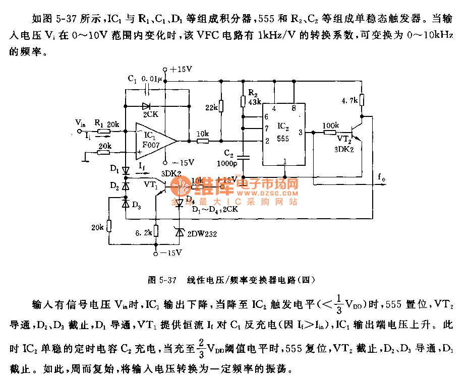
As shown in Figure 5-37, IC1 and R1, C1, D1, etc form integrator, 555 and R2, C2 etc. form monostable trigger. When the input voltage Vi changes in the range of 0 ~ 10V, the 1kHz / V conversion factor of VFC circuit can be transformed into 0 ~ 10kHz frequency. When there being the input signal voltage Vin, IC1 output declines to the trigger level of IC2, 555 sets, VT2 is conducted, D2, D3 are cut off, D1 turns on, VT1 provides constant current andanti-charge for C1. IC1's output voltage rises. At this point, IC2 monostable timing capacitor C2 charges to 2/3 VDD threshold level, the 555 resets, VT2 is off, D2, D3 are conducted, D1 closes, the input voltage is converted to a certain frequency of oscillation again and again.
Reprinted Url Of This Article:
http://www.seekic.com/circuit_diagram/555_Circuit/555_Linear_voltage___frequency_converter_circuit_4.html
Print this Page | Comments | Reading(3)

Article Categories
power supply circuit
Amplifier Circuit
Basic Circuit
LED and Light Circuit
Sensor Circuit
Signal Processing
Electrical Equipment Circuit
Control Circuit
Remote Control Circuit
A/D-D/A Converter Circuit
Audio Circuit
Measuring and Test Circuit
Communication Circuit
Computer-Related Circuit
555 Circuit
Automotive Circuit
Repairing Circuit
Code: