A/D-D/A Converter Circuit
1.2 V voltage could be turned into 9 V converter circuit diagram
Published:2014/2/24 20:16:00 Author:lynne | Keyword: 1.2 V voltage could be turned into 9 V converter circuit diagram, | From:SeekIC
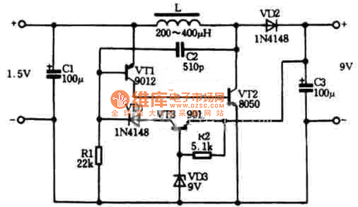
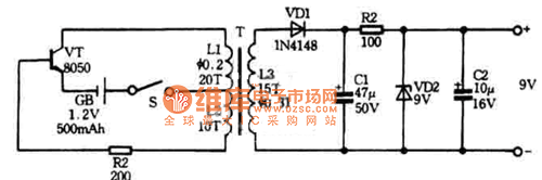
Figure 1 is a DC voltage boost circuit. The circuit can be a boost to 1.5V battery 9V, 9V laminated battery to replace. Circuit load input current is less than 1.2mA, the conversion efficiency up to 60%. The circuit consists of an oscillation circuit and voltage regulator circuit, which VT1, VT2, C2 composition oscillator, color code inductance L is the inductor, VD2 rectifier diode, C3 is the output filter capacitor, VT3, VD1, VD3 and R2 is stable the output voltage of the voltage regulator circuit. The output voltage is approximately equal to the value of VD3 of regulator. DC boost regulator circuit diagram shown in Figure 1
Figure 2 is a use of 1.2V, 500mAh nickel-cadmium batteries do power inverter circuit, the output voltage of 9V, digital multimeter available for use. Power inverter circuit shown in Figure 2
Reprinted Url Of This Article:
http://www.seekic.com/circuit_diagram/A-D_D-A_Converter_Circuit/12_V_voltage_could_be_turned_into_9_V_converter_circuit_diagram.html
Print this Page | Comments | Reading(3)

Article Categories
power supply circuit
Amplifier Circuit
Basic Circuit
LED and Light Circuit
Sensor Circuit
Signal Processing
Electrical Equipment Circuit
Control Circuit
Remote Control Circuit
A/D-D/A Converter Circuit
Audio Circuit
Measuring and Test Circuit
Communication Circuit
Computer-Related Circuit
555 Circuit
Automotive Circuit
Repairing Circuit
Code: