A/D-D/A Converter Circuit
FREQUENCY_TO_VOLTAGE_CONVERTERS
Published:2009/7/1 1:58:00 Author:May | From:SeekIC
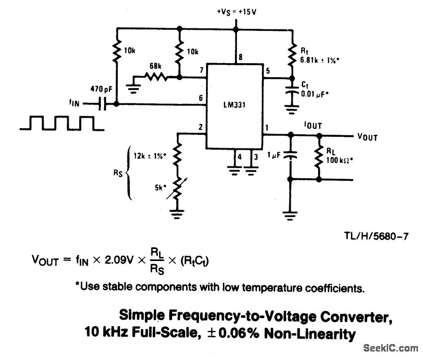
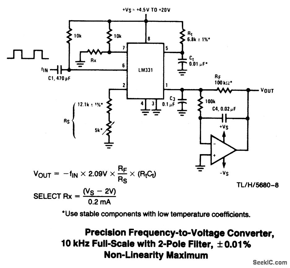
In these applications, a pulse input at fIN is differentiated by a C-R network and the negative-going edge at pin 6 causes the input comparator to trigger the timer circuit.Just as with a V-to-F converter, the average current flowing out of pin 1 is IAVERAGE = i x (1.1 R1C1) x f. In this simple circuit, this current is filtered in the network Rt = 100 k ohm and 1 μF. The ripple will be less than 10 mV peak, but the response will be slow, with a 0.1 second time constant, and settling of 0.7 second to 0.1% accuracy.In the precision circuit,an operatiot amplifier provides a buffered outputand also acts as a 2-pole filter.The ripple will be less than 5 mV peak forall frequenciesabove 1 kHz,and the response time will be much quicker than in Part 1,However,for input frequencies below 200 Hz,this circuit will have worse ripple than the figure。The engineering of the filter time-constants to get adequate response and small enough ripple simply requlres a study of the compromises to be made.Inherently V-to-Fconverter response can be fast, but F-to-Ⅴ response cannot.
Reprinted Url Of This Article:
http://www.seekic.com/circuit_diagram/A-D_D-A_Converter_Circuit/FREQUENCY_TO_VOLTAGE_CONVERTERS.html
Print this Page | Comments | Reading(3)

Article Categories
power supply circuit
Amplifier Circuit
Basic Circuit
LED and Light Circuit
Sensor Circuit
Signal Processing
Electrical Equipment Circuit
Control Circuit
Remote Control Circuit
A/D-D/A Converter Circuit
Audio Circuit
Measuring and Test Circuit
Communication Circuit
Computer-Related Circuit
555 Circuit
Automotive Circuit
Repairing Circuit
Code: