
Index 365
Two Roads Output Regulated Voltage Circuit of LTC1878
Published:2011/7/17 5:27:00 Author:Michel | Keyword: Regulated Voltage Circuit

The above picture is two roads output regulated circuit of LTC1878.It is two roads output regulated circuit composed of intergrated circuit and transformer.One road mainly outputs 1.8V/35OmA,U。1 and the other road outputs 3.3V/1OOmA U。2.It feedbacks the output voltage to chip error amplifier end via dividing voltage.The error amplifier inspires two roads output voltage.Feedback is the sum of the voltage that feedback current which flows through feedback dividing voltage.Thus,error amplifier contorls two roads output and it can make the regulated voltage degree of two roads reaches 5% when the output voltage and load change. (View)
View full Circuit Diagram | Comments | Reading(524)
Application Circuits of LT1725 and MAX699
Published:2011/7/17 5:30:00 Author:Michel | Keyword: Application Circuits
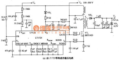
The picture a and b are application circuits of LT1725 and MAX699.The picture a is the regulated circuit of LT1725.Isolation power uses transformer and couplers etc.The isolation device adopts transformer and the controller uses LT1725.The guideline of the stable power is shown as follows.The input DC voltage is 100~300V,output voltage is 5V and output current is 1OOmA~1A.The conversion rate is 70%, regulated rate is ±3% and isolation degree is 500V (DC)when it is full load.
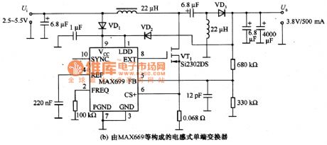
The picture b is single end transformer of induction composed of MAX699 etc. The input voltage of this kind of transformer is 2.5~5.5V and the output current can reach 500mA.The dvice is chosen according to the voltage limit.
(View)
View full Circuit Diagram | Comments | Reading(853)
Digital Comb Filter Intergrated Circuit
Published:2011/7/15 4:55:00 Author:Michel | Keyword: Filter Intergrated Circuit
SAA4961 is a PAL/NTSC comb filter (Y/C separation) integrated circuit which is widely used in big screen and various other screen color TVs.
First,Functions and Features
SAA4961 integrated circuit is a kind of adaptive,adjust-free, PAL/NTSC format compatible comb filter.It uses discrete time, amplitude and technology to process imitation interface signal.The inner circuit of SAA4961 integrated blocks consists of delay line, filter, clock processor and signal converters etc.
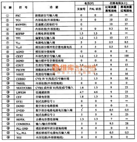
Second,Pins Functions and DataSAA4961 integrated circuit uses 28 feet dual-in-line package and its pins functions and data are shown as table 1.
Table 1:Pins Functions and Data of SAA4961 (View)
View full Circuit Diagram | Comments | Reading(633)
Constant Voltage and Current Charging Circuit of NJM2340
Published:2011/7/16 7:26:00 Author:Michel | Keyword: Constant Voltage and Current, Charging Circuit
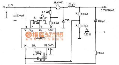
The above picture is constant voltage and current charging circuit.The input and output voltage of this circuit are 12V and 5.5V/680mA respectively and its conversion rate is 70%.NJM2340 is PWM control type constant voltage and current power supply integrated controller and there are high precision voltage and current control circuit.The dutyfactor of PWM circuit can be regulated to 100% and voltage difference between input and output voltage is very small and the conversion rate is very high.Thus,it can be used when it is low input voltage and the input voltage can be less than 6V. (View)
View full Circuit Diagram | Comments | Reading(934)
PCMl716E DAC Decoding Intergrated Circuit
Published:2011/7/16 8:18:00 Author:Michel | Keyword: Decoding Intergrated Circuit
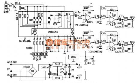
PCMl716E is senior DAC decoding integrated circuit designed by America BB company and it is designed for high-grade CD and DVD.
First,PCMl716E Functions and Features
PCMl716E adopts a modified multilevel AE which can obtain more excellent dynamic performance and reduce the chip's sensitive degree to clock jitter .It has the following main features.
(1)It is able to deal with the digital audio signal of 24 bit96KHZ specification and it also supports the the audio data of previous 16 bit 2 Obit precision.And the sampling frequency coverage is from 16 KHz to 96 KHz.
(2)Total harmonic distortion is 96 dB and dynamic range is 106 dB. (View)
View full Circuit Diagram | Comments | Reading(834)
TL594 switching regulator, main features and pin of DC-DC circuit and power supply monitor
Published:2011/7/11 5:53:00 Author:Lucas | Keyword: switching regulator, main features , pin , DC-DC circuit , power supply monitor
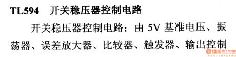
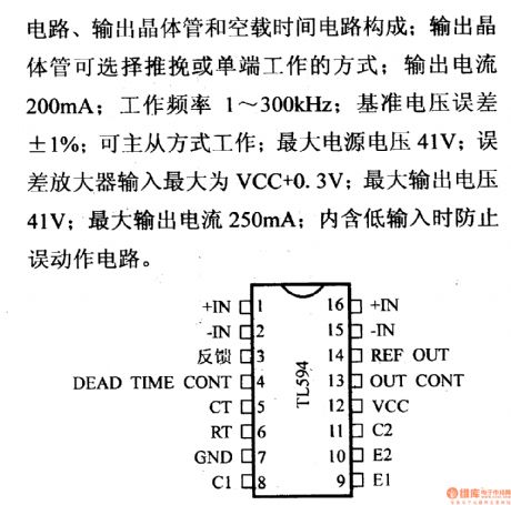
It is composed of the 5V reference voltage, oscillator, error amplifier, comparator, flip-flop, output control circuit, output transistor and load time circuit; output transistor can select single-end or push-pull working way; output current is 200mA; frequency is 1 ~ 300KHz; reference voltage is ± 1%; be the main way to work from; maximum supply voltage of 41V; error amplifier input can be up to VCC +0.3 V; the maximum output voltage is 41V; maximum output current is 250mA.
(View)
View full Circuit Diagram | Comments | Reading(860)
DC-DC Optoelectronic Isolator Circuit
Published:2011/7/11 23:57:00 Author:Michel | Keyword: Optoelectronic Isolator Circuit
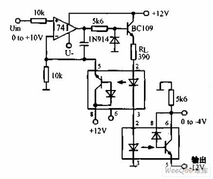
The above picture is DC-DC optoelectronic isolator circuit.The circuit is used to produce input isolation for silicon controlled converter. The above photoelectric isolator constitutes a negative feedback for the op-amp and the following photoelectric isolator completes the photoelectric signal transmission.And transmission nonlinear is within 2%.
(View)
View full Circuit Diagram | Comments | Reading(1216)
0-10 Minutes Timer Circuit with One Second Accuracy
Published:2011/7/12 2:28:00 Author:Michel | Keyword: Timer Circuit
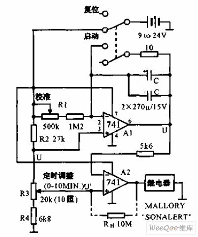

The 0-10 minutes timer circuit with one second accuracy is shown as above.It uses resistors and capacitances etc. to constitute one second accuracy timer. After it is calibrating,its accuracy has nothing to do with power voltage.Because the power supply voltage influences the charging voltage and the threshold voltage of the comparator meanwhile.The timer's delay time is CR1R3/R2. (View)
View full Circuit Diagram | Comments | Reading(654)
The Low Consumption Timer Circuit
Published:2011/7/12 2:53:00 Author:Michel | Keyword: Timer Circuit
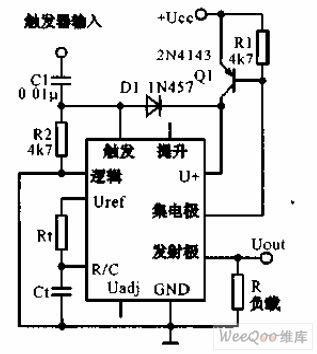
The low consumption timer uses timer IC LM122 and it provides the zero power consumption circuit in two rated cycles.The transistor Q1 stops between the two rated cycles so there is no current consumption.When 5 V or higher triggering pulse arrives and Q1 is connected and it begins to measure time. Timing time is set by the R1 and C1, its range is from a few microseconds to several hours. (View)
View full Circuit Diagram | Comments | Reading(606)
0-5 Minutes Delay Circuit of Power Frequency
Published:2011/7/14 23:39:00 Author:Michel | Keyword: Power Frequency, Delay Circuit
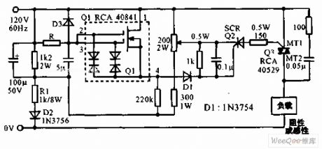
Power frequency 0-5 minutes delay circuit is shown as the above picture.This circuit uses double grid mosfet RCA40841 to constitute controlled silicon trigger circuit and the R value determines the delay time.When R is 60MΩ(LRC type CGH type resistor) and the relay time is 5 minutes and bidirectional controlled silicon can drive large current resistance loading or electrical resistance AC loading.And the error is within 10% if it is in -25~+60℃. (View)
View full Circuit Diagram | Comments | Reading(777)
The Input Loop Circuit of Amplifier Circuit
Published:2011/7/15 2:24:00 Author:Michel | Keyword: Input Loop Circuit
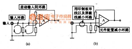
The picture (a) is the loop composed of one circle coils of the op-amp amplifier circuit input end.The magnetic will feel the electric potential when it flows through the loop and there will be noise in op-amp output part.Therefore, we need to pay attention to the components configuration and wiring,anti-noise ability can be strengthen by reducing the area of the loop, and it is shown as figure (b). (View)
View full Circuit Diagram | Comments | Reading(623)
Ultrasonic atomizer 2
Published:2011/7/17 19:25:00 Author:Lucas | Keyword: Ultrasonic atomizer
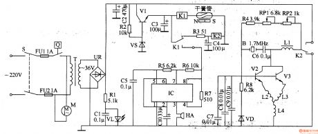
The ultrasonic atomizer circuit is composed of the power supply circuit, control circuit, water detection alarm circuit and ultrasonic oscillator, and the cirucuit is shown in Figure 3-190. Power supply circuit is composed of the power switch S, fuses FUl, FU2, timer Q, power transformer T, bridge rectifier UR, resistors Rl, R2, transistors Vl, voltage regulator diode VS, capacitors Cl, C2, and power indicator LED VL. Control circuit consists of resistor R3, capacitors C3, C4 and relays Kl, K2. Water detection and alarm circuit consists of reed switch, time-base IC rC, resistors R5-R7, capacitors C5, ClO, and buzzer HA.
(View)
View full Circuit Diagram | Comments | Reading(3319)
Ultrasonic atomizer 1
Published:2011/7/17 19:28:00 Author:Lucas | Keyword: Ultrasonic atomizer
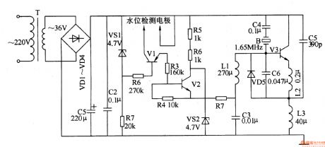
The ultrasonic atomizer circuit is composed of the power supply circuit, oscillator circuit and the water level control circuit, and the cirucuit is shown in Figure 3-189. Power supply circuit is composed of the power transformer T, rectifier diodes VDl-VD4, filter capacitors Cl, C2, zener diode VSl and resistor Rl. Water level detection control circuit consists of two electrodes, transistors Vl, V2, resistors R2-R7 and Zener diode VS2. Oscillator circuit consists of transistor V3, capacitors C3-C6, inductors Ll-L3 and the crystal ultrasonic transducer B. Rl-R7 select the 1/4W carbon film resistors or metal film resistors.
(View)
View full Circuit Diagram | Comments | Reading(4432)
Power Input Conversion Thick Membrane Integrated Circuit of STR80145 and STR80145A
Published:2011/7/15 4:14:00 Author:Michel | Keyword: Power Input Conversion, Thick Membrane Integrated Circuit
STR80145 and STR80145A are power input conversion thick membrane integrated circuits of SANKEN and they are used in various big screen color TVs.
First,Functions and Features STR80145 and STR80145A integrated circuits contain controlled silicon, the power supply voltage sampling circuit, double voltage and bridge rectifying power supply switch circuits etc.
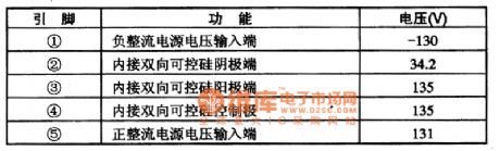
Second,Pins and DataThe pins functions and data of STR80145 and STR80145A are shown as table 1.
Table 1:Pins Functions and Data of STR80145 and STR80145A (View)
View full Circuit Diagram | Comments | Reading(746)
The typical application circuit of HJ94030 multi-function light control IC
Published:2011/7/18 5:57:00 Author:Lucas | Keyword: typical application, multi-function , light control IC
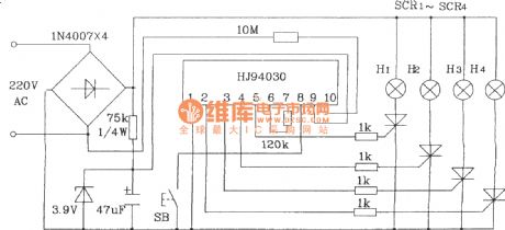
In the Figure, the button SB is used to select lights string H1 ~ H4 flashing mode, and each pressing time will change a pattern. Chip power is supplied by 220V AC and rectified by the regulator and resistor. It is a simple circuit without debugging
(View)
View full Circuit Diagram | Comments | Reading(656)
The typical application circuit of HJ94015 Christmas lights string control IC
Published:2011/7/18 19:05:00 Author:Lucas | Keyword: typical application circuit , Christmas lights , string control IC

In the Figure, Sis the working modeselection button, and SB2 is used to select piezoelectric ceramics B sound volume and light string's cycle speed.
(View)
View full Circuit Diagram | Comments | Reading(1988)
HT7713 Touching stepping dimming light circuit
Published:2011/7/18 19:08:00 Author:Lucas | Keyword: Touching , stepping , dimming light circuit
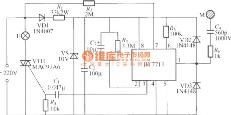
The chart shows the touching stepping dimming light circuit which is composed of HT7713, when you use it, as long as totouch M, light brightness is changed by the cycle of low light, the light, light, off, low light ... .
(View)
View full Circuit Diagram | Comments | Reading(644)
BA2181 touching stepping dimmer circuit
Published:2011/7/18 19:22:00 Author:Lucas | Keyword: touching stepping dimmer
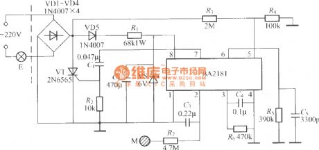
The touching steppingdimmer circuit shown as the chart uses BA2181 dimming ASIC, and it has the features of low power consumption, high anti-interference ability, stable and reliable, security work.
(View)
View full Circuit Diagram | Comments | Reading(452)
oil crop roaster controller
Published:2011/7/16 19:46:00 Author:chopper | Keyword: roaster controller
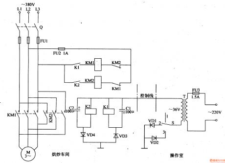
This example describes the oil crop roaster controller, which can achieve the long-distance control to roasted devices. The principle of circuit The oil crop roaster controller circuit is actual a motor single-track and remote positive and negative rotary-controlling circuit,which is shown in Figure 4-130.
Fuse FU3,power transformer T,the control switch S and diodes VD1,VD2 are installed in controller circuit of the operating room; motor M,knife switch Q, fuses FU1,FU2,AC contactors KM1,KM2,relays K1,K2,capacitors C1,C2 and diodes VD3,VD4 are installed in the blender of roaster drive circuit of roasting truck; the controller and the blender of roaster drive circuit are connected through a control line.
(View)
View full Circuit Diagram | Comments | Reading(528)
1000W LED adjustable output voltage driver power circuit
Published:2011/7/16 8:04:00 Author:Fiona | Keyword: adjustable output voltage, driver

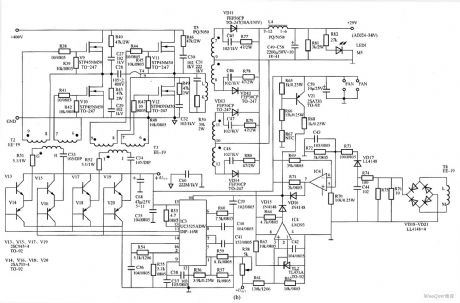
Figure (a) is 1000W LED adjustable output voltage driver PFC and auxiliary power supply circuit,including input rectifier filter circuit,EMI suppression circuit, power factor correction circuit and auxiliary power supply circuit; Figure (b) is l000W LED adjustable output voltage drive full-bridge converter circuit, including full-bridge driver circuit,full-bridge converter circuit,the output rectifier filter circuit,PWM control circuit and various protection circuits.
(View)
View full Circuit Diagram | Comments | Reading(4591)
| Pages:365/471 At 20361362363364365366367368369370371372373374375376377378379380Under 20 |
Circuit Categories
power supply circuit
Amplifier Circuit
Basic Circuit
LED and Light Circuit
Sensor Circuit
Signal Processing
Electrical Equipment Circuit
Control Circuit
Remote Control Circuit
A/D-D/A Converter Circuit
Audio Circuit
Measuring and Test Circuit
Communication Circuit
Computer-Related Circuit
555 Circuit
Automotive Circuit
Repairing Circuit