
Index 366
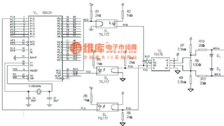
The 485 interface circuit diagram
Published:2011/7/14 21:36:00 Author:zj | Keyword: The 485 interface
View full Circuit Diagram | Comments | Reading(915)
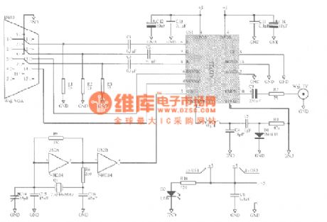
Homemade VGA-TV interface circuit diagram
Published:2011/7/14 21:39:00 Author:zj | Keyword: Homemade, VGA-TV interface
View full Circuit Diagram | Comments | Reading(2146)
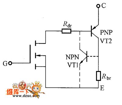
Driving Circuit By Using Speed-Up Capacitor
Published:2011/7/16 9:32:00 Author:Robert | Keyword: Driving, Speed-Up Capacitor
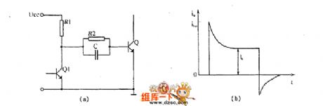
The picture shows the driving circuit by using speed-up capacitor. (View)
View full Circuit Diagram | Comments | Reading(1576)
One Normal Type Driving Circuit
Published:2011/7/16 9:08:00 Author:Robert | Keyword: Normal, Driving
The picture shows the one normal type driving circuit. (View)
View full Circuit Diagram | Comments | Reading(480)
MC3373 infrared remote control receiving pre-S amplification and coding signal processing circuit
Published:2011/7/14 9:10:00 Author:Christina | Keyword: infrared remote control, receiving, pre-S, amplification, coding signal, processing circuit
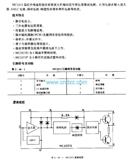
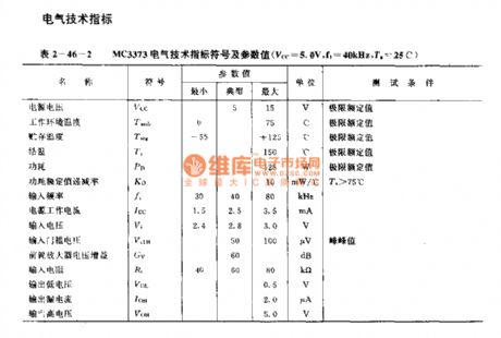
The MC3373 is designed as the infrared remote control receiving pre-S amplification and coding signal processing circuit. The internal circuit is composed of the input amplifier, the ABLC circuit, the phase shifting circuit, the peak detector and the shaping circuit.
Features
The quiescent current is low;The voltage range of the operating power supply is wide;The gain of the preamplifier circuit is high;The pulse code modulation (PCM) and the demodulation use the envelope wave-detection;The volume is small, the external components is few;It can work in the narrow band and low noise tuning circuit;The MC3373D uses the 8-pin flat plastic package;The MC3373P uses the 8-pin dual-row DIP plastic package.
(View)
View full Circuit Diagram | Comments | Reading(661)
Rectifier circuit composed of the light-emitting diode
Published:2011/7/16 5:41:00 Author:Christina | Keyword: Rectifier, light-emitting diode
Rectifier circuit composed of the light-emitting diode (View)
View full Circuit Diagram | Comments | Reading(361)
Single-phase full-bridge PWM rectifier circuit diagram
Published:2011/7/16 5:40:00 Author:Christina | Keyword: Single-phase, full-bridge, PWM, rectifier, circuit, diagram
Single-phase full-bridge PWM rectifier circuit diagram (View)
View full Circuit Diagram | Comments | Reading(567)
ICBT Iternal Equivalent Circuit
Published:2011/7/16 22:17:00 Author:nelly | Keyword: Equivalent Circuit
View full Circuit Diagram | Comments | Reading(424)
High Speed Gate Driving Circuit
Published:2011/7/16 22:44:00 Author:nelly | Keyword: High Speed, Gate Drive
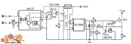
The high speed gate driving circuit shown in the picture is composed of 6N137and TK75050. In the circuit, the electric level conversion transistor VT1 applies the 2SA1460 type high speed switch transistor. TK75050 drives the IC for the power MOSFT, and the low level of its input Threshold voltage is 1V,and the high level is 1.6V. The 12V power is the 5V working voltage which is provided by 6M37 through the three-end integrated stabilizer. (View)
View full Circuit Diagram | Comments | Reading(946)
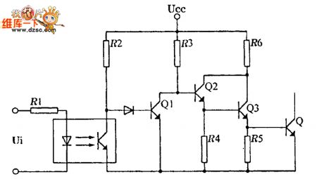
Gate Isolated Drive Circuit With The Optocoupler
Published:2011/7/16 22:42:00 Author:nelly | Keyword: Gate Isolated, Drive Circuit, Optocoupler
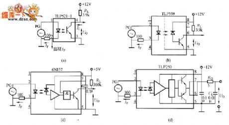
Picture B has given the high-speed optocoupler. This high -speed optocoupler is composed of GaAlAsLED, PN Photodiode output and the Current amplification transistor. The TLP559 input current and output current have the good linear relationship which can be used in the analog circuit. The current transmitting ratio is very small, which is only 40%; the up and down current transmitting delay times are 2000ns and 300ns,Therefore, the transmitting ratio is much higher than TLP521. (View)
View full Circuit Diagram | Comments | Reading(2318)
Gate Isolated Practical Driving Circuit
Published:2011/7/16 22:54:00 Author:nelly | Keyword: Gate Isolated, Practical
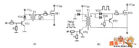
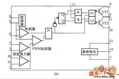
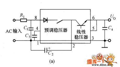
The gate isolated practical driving circuit shown in the picture applies the Pulse transformer. Picture(a) is the simple driving circuit which can control the power in the process of adjustable supply, and its duty circle is 50%. Picture(B) is the gate driving circuit which applies the PWM control, and its duty circle can be changed largely.
(a) simple driving circuit; (b)the driving circuit which has the adjustable duty circle.
Figure, gate isolated practical driving circuit (View)
View full Circuit Diagram | Comments | Reading(1272)
The Gate Isolated driving Circuit with Adjustable Duty Circle
Published:2011/7/16 23:03:00 Author:nelly | Keyword: Gate Isolated, driving, Adjustable, Duty Circle
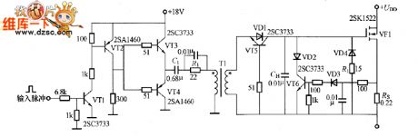
The gate isolated driving circuit shown in the picture applies the pulse transformer. This is the low-impedance output driving circuit which is composed of VT3 and VT4. In order to reduce the DC consumption, the isolated capacitor C1 is added to the circuit. VD1~VD4 selects the low drop voltage Schottky diode, VD4 and R1 are used to limit the negative peak voltage which is produced when the VF1 is limited.
Fig, The Gate Isolated driving Circuit with Adjustable Duty Circle (View)
View full Circuit Diagram | Comments | Reading(814)
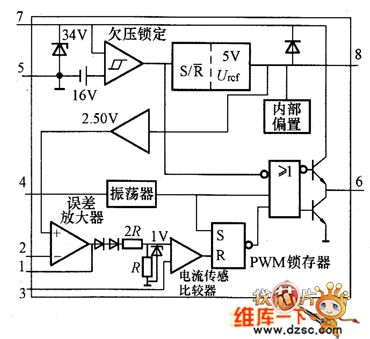
The Internal Equivalent Circuit Of UC3842 Switch Power Integrated Controller
Published:2011/7/16 23:56:00 Author:nelly | Keyword: Internal, Equivalent, Switch Power, Integrated Controller
View full Circuit Diagram | Comments | Reading(935)
The Internal Equivalent Circuit of TL494 Switch Supply Integrated Controller
Published:2011/7/17 5:10:00 Author:nelly | Keyword: Internal Equivalent, Switch, Supply, Integrated Controller
View full Circuit Diagram | Comments | Reading(940)
HV1205/HV2405E Internal Equivalent Circuit
Published:2011/7/17 5:14:00 Author:nelly | Keyword: Internal, Equivalent
The HV1205/HV2405E internal equivalent circuit is as shown: (View)
View full Circuit Diagram | Comments | Reading(496)
The Circuit of HIP5600 DC Output
Published:2011/7/17 5:15:00 Author:nelly | Keyword: DC Output
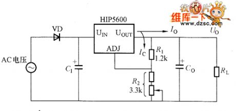
The(View)
View full Circuit Diagram | Comments | Reading(681)
Adjustable voltage transmitting circuit
Published:2011/7/16 23:07:00 Author:nelly | Keyword: Adjustable, voltage transmitting
View full Circuit Diagram | Comments | Reading(426)
Unfired bricks moisture viewer 1
Published:2011/6/26 22:21:00 Author:Nicole | Keyword: Unfired brick, moisture, viewer
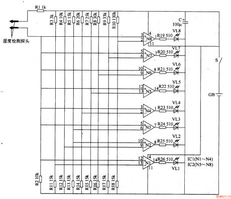
This unfired bricks moisture detector circuit is composed of humidity detector probe, operation amplifiers N1-N8(IC1, IC2), LEDs(VL1-VL8)and resistors R1-R26, it is shown in the figure 8-75.
After the power supply switch S is connected, the unfired bricks moisture detector circuit starts to work. When the humidity detector probe inserts the unfired bricks, it will produce a resistance value on the two sides of probe which changes with the water content of unfired bricks, this resistance value is amplified and processed by operation amplifiers N1-N8, the water content of unfired bricks is displayed by LEDs VL1-VL8 which is out-connected on the N1-N8 output terminal.
(View)
View full Circuit Diagram | Comments | Reading(491)
Ozone disinfector 11
Published:2011/6/30 1:28:00 Author:Nicole | Keyword: ozone disinfector

The push-pull oscillation circuit is composed of transistors V1, V2, oscillation transformer T2(W1-W3), pulse transformer T1, current limiting resistor R1, charge capacitor C3, two-way trigger diode VD5.
The half wave rectifier filter circuit is made of filter inductance coil L, rectifier diode VD1 and filter capacitors C1, C2.
The power supply is turned on, 220V AC voltage is filtered by L, it is rectifiered by VD1, it will produce about +280V voltage on the two sides of C1, it feeds to push-pull oscillation circuit.
When it is power on, V1 is turned on, due to C3's charge, two-way trigger diode VD5 is cut off.
(View)
View full Circuit Diagram | Comments | Reading(643)
Plane shaking table governor
Published:2011/7/1 1:05:00 Author:Nicole | Keyword: shaking table, governor
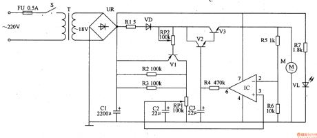
The plane shaking table governor circuit is composed of power supply input circuit and environment speed regulation control circuit, it is shown in the figure 9-159.
The power supply input circuit is made of fuse FU, power switch S, power transformer T, bridge rectifiers UR, filter capacitor C1, current limiting resistor R7 and power indication LED VL.
The speed regulation control circuit consists of resistors R1-R6, potentiometers RP1, RP2, capacitors C2, C3, diode VD, transistors V1-V3, operation amplifier IC and motor M.
(View)
View full Circuit Diagram | Comments | Reading(773)
| Pages:366/471 At 20361362363364365366367368369370371372373374375376377378379380Under 20 |
Circuit Categories
power supply circuit
Amplifier Circuit
Basic Circuit
LED and Light Circuit
Sensor Circuit
Signal Processing
Electrical Equipment Circuit
Control Circuit
Remote Control Circuit
A/D-D/A Converter Circuit
Audio Circuit
Measuring and Test Circuit
Communication Circuit
Computer-Related Circuit
555 Circuit
Automotive Circuit
Repairing Circuit