
Index 367
Electronic snore-ceasing equipment 2
Published:2011/6/27 3:57:00 Author:Nicole | Keyword: Electronic snore-ceasing equipment
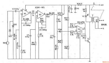
The snoring detection circuit is made of microphone BM, limiter diodes VD1, VD2, coupling capacitor C1 and selection frequency component R1, C2.
The preposition amplifier circuit consists of operation amplifier integrated circuit IC(N1-N3)internal operation amplifier N1, N2 and peripheral device.
The pulse generation circuit(belong to low frequency self-exciting oscillator)is composed of IC internal operation amplifier N3 and peripheral resistor capacitor components.
The pulse change circuit is made of switch tube V, boost transformer T and potentiometer RM.
(View)
View full Circuit Diagram | Comments | Reading(575)
Thermometer meter slinger 1
Published:2011/6/29 20:06:00 Author:Nicole | Keyword: thermometer, meter slinger
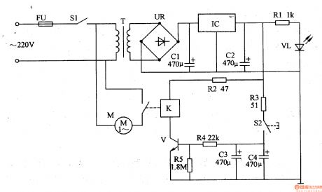
The thermometer meter slinger circuit is composed of power supply circuit and meter slinger timing control circuit, it is shown in the figure 9-134.
The power supply circuit is made of fuse FU, power supply switch S1, power transformer T, bridge rectifiers UR, filter capacitors C1, C2, there terminals steady voltage integrated circuit IC, current limiting resistor R1 and power supply indication LED VL.
After power supply switch S1 is turned on, 220V AC voltage is stepped down by T, it is rectified by UR, it is filtered by C1, it is stabilized by IC, it provides the timing control circuit with +12V voltage. +12V voltage is current limited and stepped down by R1, then it lights VL.
(View)
View full Circuit Diagram | Comments | Reading(630)
Negative oxygen ion generator 6
Published:2011/6/28 2:01:00 Author:Nicole | Keyword: oxygen ion, generator
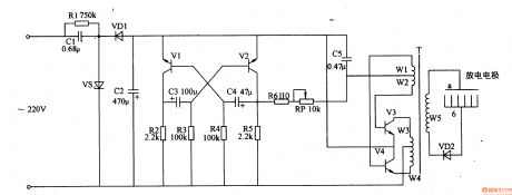
This negative oxygen ion generator circuit is composed of power supply circuit, multivibrator and high voltage circuit, it is shown in the figure 9-118.
The power supply circuit is made of capacitors C1, C2, resistor R1, steady voltage diode VS and rectifier diode VD1.
The multivibrator consists of transistors V1, V2, resistors R2-R5 and capacitors C3, C4.
The high voltage circuit is composed of capacitor C5, resistor R6, potentiometer RP, transistors V3, V4, high voltage transformer T, high voltage rectifier diode VD2 and high voltage discharge electrodes a, b.
(View)
View full Circuit Diagram | Comments | Reading(1287)
Negative oxygen ion generator 5
Published:2011/6/28 1:51:00 Author:Nicole | Keyword: oxygen ion, generator
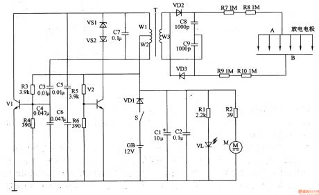
This negative oxygen ion generator circuit is composed of power supply circuit, multivibrator, high voltage discharge circuit and fan circuit, it is shown in the figure 9-117.
The power supply circuit is made of power supply switch S, battery GB, diode VD1, capacitors C1, C2, resistor R1 and LED VL.
The multivibrator consists of transistors V1, V2, resistors R3-R6, capacitors C3-C7, steady voltage diodes VS1, VS2 and windings W1, W2 of pulse transformer T.
The high voltage discharge circuit is composed of twice winding(W3) of T, diodes VD2, VD3, capacitors C8, C9, resistors R7-R10 and discharge electrode.
(View)
View full Circuit Diagram | Comments | Reading(2376)
Negative oxygen ion generator 4
Published:2011/6/28 1:33:00 Author:Nicole | Keyword: oxygen ion, generator
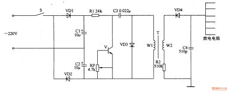
This negative oxygen ion generator circuit is composed of full wave dual voltage rectifier circuit, pulse oscillation circuit and negative high voltage generation circuit, it is shown in the figure 9-116.
The dual voltage rectifier circuit is made of diodes VD1, VD2, and capacitors C1, C2.
The pulse oscillation circuit consists of transistor V, resistor R1, potentiometer RP, capacitor C3, diode VD3 and once winding of boost transformer T.
The negative high voltage generation circuit is composed of twice winding of T, high voltage silicon rectifier stack VD4, resistor R2 and capacitor C4.
(View)
View full Circuit Diagram | Comments | Reading(5218)
Medical ultrasonic atomizer 2
Published:2011/6/29 22:40:00 Author:Nicole | Keyword: ultrasonic atomizer
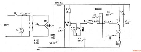
The medical ultrasonic atomizer circuit is composed of power supply circuit, atomization amount liquid level detection control circuit, ultrasonic oscillator and fan motor M, it is shown in the figure 9-111.
The power supply circuit is made of timer Q, fuses FU1, FU2, power transformer T, bridge rectifiers UR, resistors R1, R2, LED VL and filter capacitor C1.
The atomization amount/liquid level detection control circuit consists of resistor R3, potentiometers RP1, RP2, magnetic control water level switch SA(it is composed of float with magnetic ring and reed switch)and capacitor C2.
(View)
View full Circuit Diagram | Comments | Reading(4302)
Medical ultrasonic atomizer 1
Published:2011/6/29 22:27:00 Author:Nicole | Keyword: ultrasonic atomizer
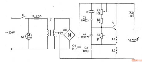
The medical ultrasonic atomizer circuit is composed of power supply circuit, ultrasonic oscillator and atomizer circuit, it is shown in the figure 9-110.
The power supply circuit is made of timer Q, fuse FU, current transformer T, bridge rectifiers UR, current limiting resistor R2, power supply indication LED VL and filter capacitor C4.
The ultrasonic oscillator circuit consists of transistor V, resistor R1, potentiometer RP, thermal resistor RT, capacitorS C2, C3 and inductors L1, L2.
The atomizer circuit is composed of piezoelectric ultrasonic transducer B, capacitor C1 and fan motor M.
(View)
View full Circuit Diagram | Comments | Reading(7491)
Motor light load energy saver 2
Published:2011/6/30 0:59:00 Author:Nicole | Keyword: motor, light load energy saver
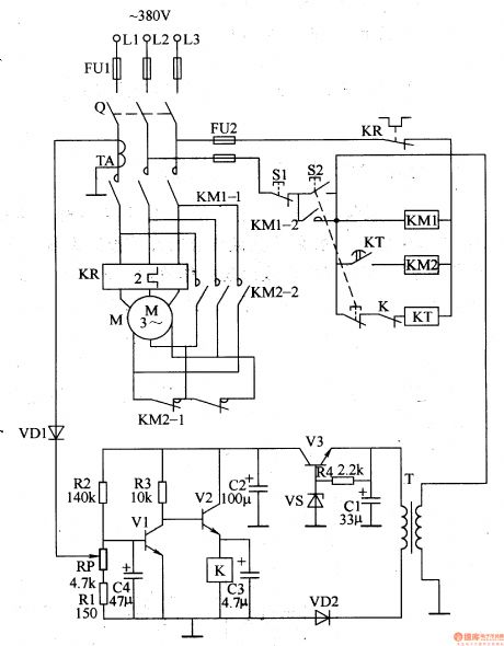
The motor light load energy saver circuit is composed of power supply circuit, current sampling detection circuit and control circuit, it is shown in the figure 8-2.
The power supply circuit is made of power transformer T, voltage regulation tube VS, rectifier diode VD2, resistor R4 and filter capacitors C1, C2.
The control circuit consists of power supply switch Q, stop button S1, starter button S2, transistors V1, V2, relay K, time relay KT, AC contactor KM1, KM2.
(View)
View full Circuit Diagram | Comments | Reading(1097)
Ozone disinfector 12
Published:2011/6/30 1:36:00 Author:Nicole | Keyword: ozone disinfector
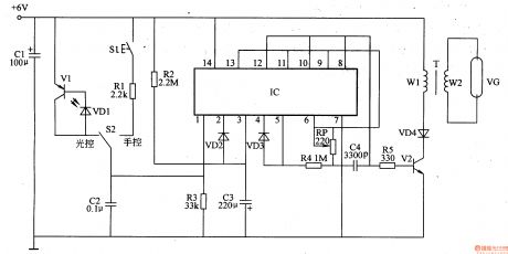
The ozone disinfector circuit is composed of hand control/optical control convert circuit, delay control circuit, oscillator and high voltage generator circuit, it is shown in the figure 9-109.
The hand control/optical control convert circuit is made of photosensitive diode VD1, transistor V1, transfer switch S2, hand control button S1, resistor R1.
The delay control circuit consists of six not gates integrated circuit IC, resistor R3, capacitors C2, C3 and diodes VD2, VD3.
The oscillator circuit is composed of IC and resistors R2, R4, potentiometer RP, capacitor C4.
(View)
View full Circuit Diagram | Comments | Reading(783)
Music socket circuit diagram with infrared sensor application-specific integrated circuit using KC778B
Published:2011/5/17 3:17:00 Author:Ecco | Keyword: Music socket, application-specific integrated circuit , infrared sensor
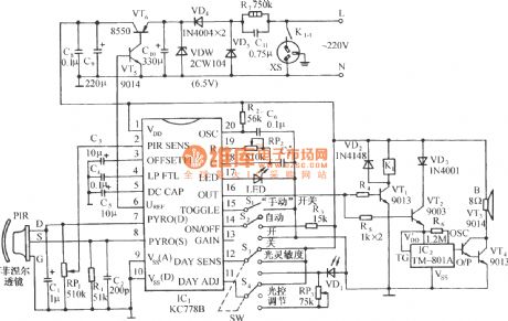
The chart shows the music socket circuit diagram with infrared sensor specific integrated circuit using KC778B. KC778B is a type of infrared sensor specific integrated circuit which is supported to use with pyroelectric infrared sensors, and they could be used as automatic lights, automatic doors, automatic electric fans, air conditioning, automatic release device and security alarm system. (View)
View full Circuit Diagram | Comments | Reading(1445)
Ozone disinfector 10
Published:2011/6/30 1:16:00 Author:Nicole | Keyword: ozone disinfector
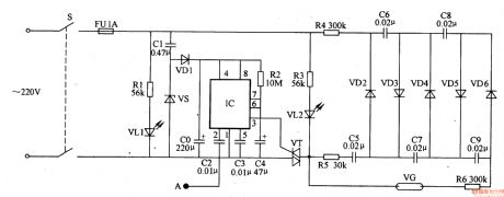
The ozone disinfector circuit is composed of delay circuit, power supply circuit, double-pressure ozone generation circuit and some correlative components, it is shown in the figure 9-107.
The delay circuit is made of time base integrated circuit IC and capacitors C2, C4.
The power supply circuit consists of steady voltage diode VS, rectifier diode VD1, capacitors C1, C0.
The double-pressure ozone generation circuit is composed of rectifier diode VD2-VD6, capacitors C5-C9, resistor R6, ozone tube VG.
(View)
View full Circuit Diagram | Comments | Reading(841)
Ozone disinfector 9
Published:2011/6/30 1:08:00 Author:Nicole | Keyword: ozone disinfector
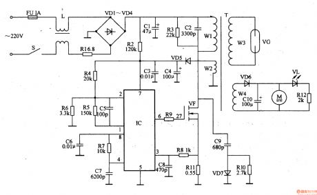
The ozone disinfector circuit is composed of power supply input circuit, switch oscillation circuit, fan circuit and ozone generator circuit, it is shown in the figure 9-106.
The power supply input circuit is made of fuse FU, power supply switch S, filter inductor L, current limiting resistor R1, rectifier diodes VD1-VD4 and filter capacitor C1.
The switch oscillation circuit consists of PWM switch power supply control integrated circuit IC, resistors R2-R11, capacitors C2-C9, diodes VD5, VD7, FET VF and the W1, W2 winding of switch pulse transformer T.
(View)
View full Circuit Diagram | Comments | Reading(3392)
Negative oxygen ion generator 3
Published:2011/6/28 1:23:00 Author:Nicole | Keyword: oxygen ion, generator
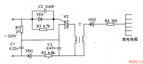
This negative oxygen ion generator circuit is composed of TRIAC VT, diodes VD1-VD3, resistors R1-R4, capacitors C1-C3, boost transformer T and electrode pad, it is shown in the figure 9-115.
The bleeder circuit is made of R1 and C1, the phase shift trigger circuit consists of VD1, C2, R3.
At the negative half-cycle of AC, rectifier diode VD2 turns on, after rectifying, the pulse DC voltage charges to C3 by R2, when the both sides of C3's voltage reaches peak value, VT is triggered and turned on. When the AC passage zero, due to C2's phase shift action, C2's voltage also can make VT turned on.
(View)
View full Circuit Diagram | Comments | Reading(2660)
74 series digital circuit of 74L51 and 74LS51 2 input/3 output and-nor gate
Published:2011/5/17 3:23:00 Author:Ecco | Keyword: digital circuit, 2 input, 3 output, and-nor gate
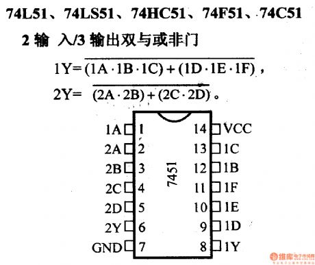
74L51, 74LS51, 74HC51, 74F51, 74C51 2 and-nor gate
(View)
View full Circuit Diagram | Comments | Reading(742)
Negative oxygen ion generator 2
Published:2011/6/28 1:07:00 Author:Nicole | Keyword: oxygen ion, generator
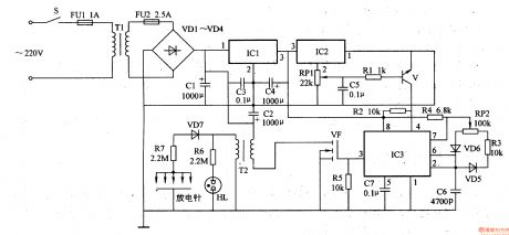
This negative oxygen ion generator circuit is composed of power supply circuit, humidity detection circuit, oscillator and high voltage generator, it is shown in the figure 9-114.
The power supply circuit is made of power supply switch S, fuse FU1, FU2, power transformer T1, rectifier diodes VD1-VD4, fliter capacitors C1-C3, there terminals integrated regulator IC1.
The humidity detection circuit consists of integrated circuit IC2, control tube V, potentiometer RP1, resistor R1 and capacitor C5.
The oscillator is composed of time base integrated circuit IC3 and peripheral devices.
(View)
View full Circuit Diagram | Comments | Reading(1929)
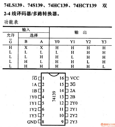
74 series digital circuit of 74LS139 and 74S139 2-4 line decoder/multi-channel converter
Published:2011/5/17 3:18:00 Author:Ecco | Keyword: digital circuit , 2-4 line decoder, multi-channel converter
View full Circuit Diagram | Comments | Reading(2579)
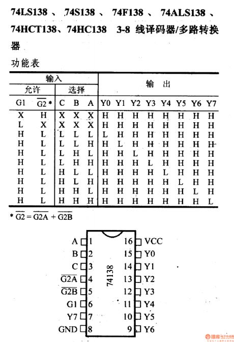
74 series digital circuit of 74LS138 and 74S138 3 - 8 line decoder/multiplexer
Published:2011/5/17 3:19:00 Author:Ecco | Keyword: digital circuit, 3 - 8 line decoder, multiplexer
View full Circuit Diagram | Comments | Reading(4064)
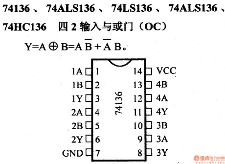
74 series digital circuit of 74136 and 74ALS136 four 2 input and nor gate(OC)
Published:2011/5/17 3:21:00 Author:Ecco | Keyword: digital circuit , four 2 input, nor gate
View full Circuit Diagram | Comments | Reading(1095)
74 series digital circuit of 74LS112A 74F112 double J - K negative edge trigger
Published:2011/5/17 3:21:00 Author:Ecco | Keyword: digital circuit , double J - K negative edge, trigger
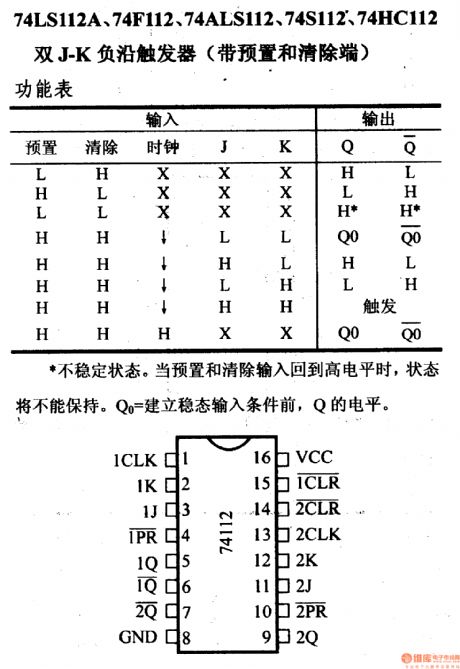
74 series digital circuit of 74LS112A,74F112 double J - K negative edge trigger( with preset and remove terminal)
(View)
View full Circuit Diagram | Comments | Reading(1303)
74 series digital circuit of 7473 and 74H73 input J - K master-slave flip-flop
Published:2011/5/17 3:22:00 Author:Ecco | Keyword: digital circuit, input J - K, master-slave flip-flop
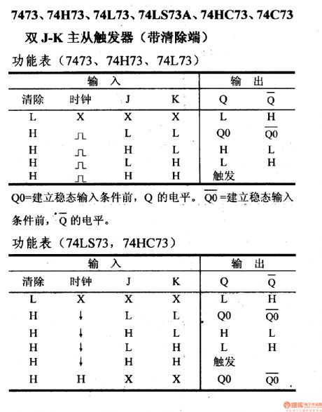
7473, 74H73,74L73, 74LS73A, 74HC73, 73C73double J - K master-slave flip-flop(with remove terminal)
The level of Qo is equal to Q before eatablishing steadystate input. (View)
View full Circuit Diagram | Comments | Reading(1742)
| Pages:367/471 At 20361362363364365366367368369370371372373374375376377378379380Under 20 |
Circuit Categories
power supply circuit
Amplifier Circuit
Basic Circuit
LED and Light Circuit
Sensor Circuit
Signal Processing
Electrical Equipment Circuit
Control Circuit
Remote Control Circuit
A/D-D/A Converter Circuit
Audio Circuit
Measuring and Test Circuit
Communication Circuit
Computer-Related Circuit
555 Circuit
Automotive Circuit
Repairing Circuit