
Index 370
Multichannel infrared remote control circuit diagram composed of LM567
Published:2011/5/13 4:28:00 Author:Ecco | Keyword: Multichannel , infrared remote control
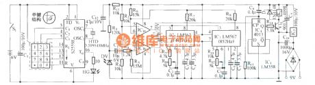
LM567 is a PLL audio decoding circuit
(View)
View full Circuit Diagram | Comments | Reading(1185)
Panasonic NV-L15 VCR breakdown maintenance circuit diagram
Published:2011/6/24 3:59:00 Author:Ecco | Keyword: Panasonic , VCR , breakdown maintenance
Fault phenomenon: When it is connected to the power, the display has a clock display. Pressing the power switch and turning on the power, but the cassette tape can not be pullin into storage box. Analysis and Maintenance: The chart shows the connection circuit with box. Under normal circumstances, when the cartridge is pulled into the cassette, the mechanical transmission mechanism of storage with box will drive the switch with box which is intalled on the right side of plastic bracket in mechanism components with storage box. The switch with box has three different sliding contact positions of A, B, C , which are used to monitor the tape location in the box and notify the microprocessor (CPU) to issue the appropriate instructions.
(View)
View full Circuit Diagram | Comments | Reading(1299)
Household AC voltage regulator principle and maintenance circuit diagram
Published:2011/6/24 4:05:00 Author:Ecco | Keyword: Household, AC voltage regulator, principle , maintenance
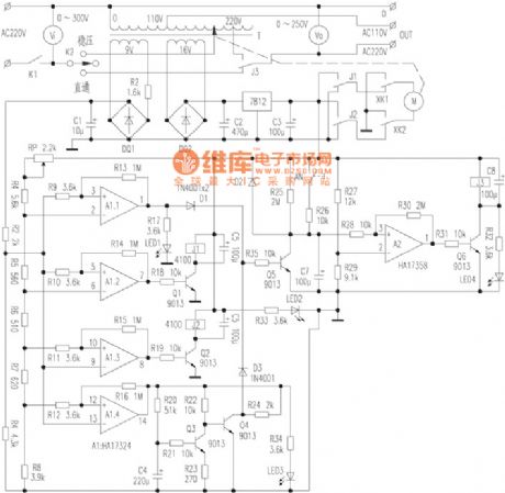
The Dadi TJ30 3kW AC voltage regulator electrical schematic is shown as the chart. The whole machine can be divided into two parts of the main circuit and control circuit, and Vi and Vo are the input and output tables. The main circuit is the path of the AC power from input end to output end, and the path includs air switch K1, regulator and direct connection selecting switch K2, regulator transformer T, delay control relay J3 and input and output wiring terminals and other components. Control circuit has the functions of power delay transmission, stable output voltage, overvoltage protection and instructions, undervoltage protection and indication.
(View)
View full Circuit Diagram | Comments | Reading(1404)
The saving lamp circuit diagram and maintenance
Published:2011/6/24 3:06:00 Author:Ecco | Keyword: saving lamp , maintenance
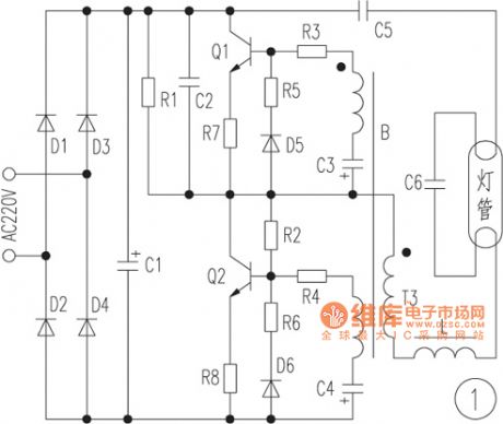
The saving lamp circuit has the glass cover type and exposed type. Glass cover types have three series of spherical, cylindrical ball, processing type, etc. , the first two series have completely four types of transparent, carving, engraving and white color. It has the advantages of beautiful appearance, easy installation, anti-collision, etc.; exposed type has the types of H, UH-based, 3U, 4U-based, 2D and screw type. They also can be divided by the color of light, which can be divided into red, green, blue, yellow (color temperature is 2700K, and it belons to warm light which is similar to incandescent light color), white (color temperature is 6400K, is a cool light which similar to fluorescent light color); the lamps with color temperature in 5000K has no irritation to the eyes as the light color close to natural light.
(View)
View full Circuit Diagram | Comments | Reading(497)
A linear three-terminal regulator expansion flow circuit diagram
Published:2011/6/24 2:16:00 Author:Ecco | Keyword: linear , three-terminal , regulator , expansion flow
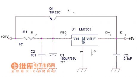
This circuit is an ususal linear three-terminal regulator expansion flow circuit. 1. Drawback of source; 1.1 The power supply is a linear regulator circuit, of which all have their own internal power loss, and voltage drops result in heat loss, and the low efficiency needs us pay special attention on heat issues. 1.2 As the working speed of core component in 7805 is not too high, it has slow response to rapid changes of the input voltage or load current; 1.3 This circuit does not increase the power protection circuit because 7805 itself has overcurrent and temperature protection.
(View)
View full Circuit Diagram | Comments | Reading(534)
BCD code LED digital display components frame circuit diagram
Published:2011/5/17 4:18:00 Author:Ecco | Keyword: BCD code, LED , digital , display , components , frame
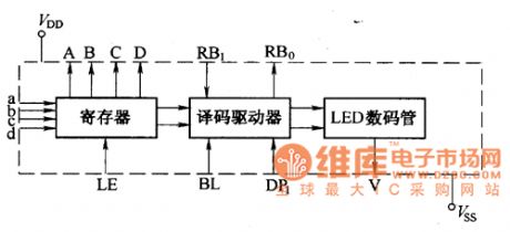
BCD code LED digital display component is a type of display module composed of strong drive CMOS integrated circuit and LED digital display, it has the triple functions of BCD code storaging, decoding drive, LED display.
(View)
View full Circuit Diagram | Comments | Reading(442)
LED +/- symbol display components appearance circuit diagram
Published:2011/5/17 4:17:00 Author:Ecco | Keyword: LED, +/- , symbol, display components, appearance
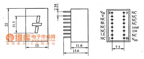
CL300 Series of LED ± symbol display components have the features of low power consumption, high reliability, long life and other characteristics, they are mainly used in digital instruments, meters and all kinds of digital electronic devices as + , - symbol display. Its shape is shown as the chart.
(View)
View full Circuit Diagram | Comments | Reading(459)
TOP2l2Y/P/G-PWM single chip switch source integrated circuit
Published:2011/7/13 20:11:00 Author:leo | Keyword: PWM, single chip, integrated circuit
TOP212 is a kind of PWM single chip switch source integrated circuit which is made by Power company in America. It is widely used in DVD, VCD, computer and LCD, air conditioner control system and other home appliances switch power source circuit.
TOP212Y/P/G has three packages which is different from each other from the suffix.(1)TOP212Y. It uses TO-220 package and has small thermal slug. The chip of thermal slug is connected to source S port and belongs to the classical signal line and three ports part.(2)TOP212P. It uses DIP-8 package which belongs to dual line eight pins package. And its pin ①-③ and ⑥-⑧ all connect to source S port. (View)
View full Circuit Diagram | Comments | Reading(460)
ZIVA D6 MPEG-2 decoding intergrated circuit diagram
Published:2011/7/13 19:39:00 Author:leo | Keyword: Decoding intergrated circuit, MPEG-2/2 audio
(View)
View full Circuit Diagram | Comments | Reading(234)
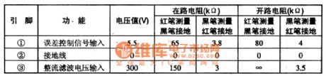
WE9142 Microcomputer dialing integreated circuit
Published:2011/7/13 19:41:00 Author:leo | Keyword: Microcomputer, dialing integrated circuit
WE9142 is a kind of microcomputer dialing integrated circuit which is widely used in all kinds of telephones.The integrated circuit WE9142 adopts 22-pin dual-line package. Pin function and related data are show in the picture, please check. (View)
View full Circuit Diagram | Comments | Reading(398)
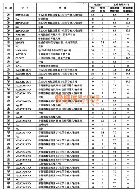
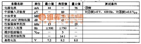
VS1001K MPS decoding integrated circuit
Published:2011/7/13 19:41:00 Author:leo | Keyword: MPS decoding integrated circuit, VLSI Solution
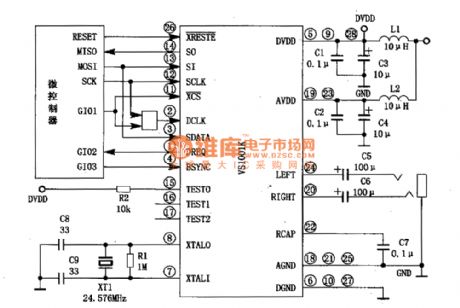
VS100K is a new type of MPS decoding integrated circuit made by VLSI Solution, which is widely used in all kinds of MPS players.
Function Features:The integrated circuit VS1001K contains stereo analog converter DAC and earphone driving circuit. It supports PCM data input and has VS-DSP processor as well as ROM and RAM. Besides, it has constant connecting data interfaces as the picture shows.
Pin Function:It adopts 28-pin SOIC dual-line and 49-pin BGA package. All information is shown in the picture. (View)
View full Circuit Diagram | Comments | Reading(1139)
MC13007-Single television small signal processing circuit
Published:2011/7/13 19:42:00 Author:leo | Keyword: Small signal processing circuit, 200 linear circuits
MCI3007 is a kind of integrated circuit made by Motorola. It contains 200 linear circuits and 200 logic circuits. It can be used to clear all small signals processing circuit except accompanying sound signals. It contains intermediate frequency amplifier, video detector, video processing circuit, noise control circuit and so on. Its inner circuit diagram and pin functions are shown in the picture.
The function of MC13007 has following features:
Video detector adopts whole wave detecting circuit. Usually, the common wave detector uses synchronous wave detecting circuit but MC113007 uses balanced diode whole wave detecting circuit.
It has multi function video processing circuit.
Its oscillator circuit adopts double horizontal frequency mode. (View)
View full Circuit Diagram | Comments | Reading(545)
The e-control circuit of the heat release electric sensor
Published:2011/7/14 6:31:00 Author:Borg | Keyword: e-control circuit, electric sensor
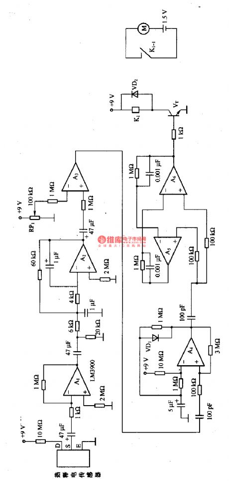
This is the e-control circuit of the heat release electric sensor. In the circuit, A1 is the amplifier circuit whose gain is 60dB, which amplifies the weak signal of the heat release sensor; A2 is the active filter whose block frequency is about 10Hz, which is used to filter the noise and wave; A3 is the comparator circuit, whose comparing value is set by RP1, A3 outputs the constant LEV signal; A4 is the single stable multiple resonance oscillator, which is used to make sure the circuit only reacts tothe signal of one sensor within a certain time when there are more than one heat release sensors.
(View)
View full Circuit Diagram | Comments | Reading(410)
MB94918-AG3-Vice micro computer and vice photo MID screen show control integrated circuit
Published:2011/7/13 19:43:00 Author:leo | Keyword: Vice micro computer, vice photo MID screen, Mitsubishi
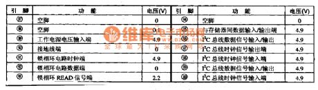
MB94918-AG3 is a kind of vice micro computer and vice photo MID screen show control integrated circuit made by Mitsubishi, which is widely used in sony series big screen television.Pin functions and data:MB94918-AG3 adopts 100 pins dual-line construction. Its pin functions and related data are shown in the picture. (View)
View full Circuit Diagram | Comments | Reading(462)
measuring temperature circuit diagram of TSV type temperature sensor using constant current
Published:2011/7/12 3:45:00 Author:Lena | Keyword: temperature sensor, constant current
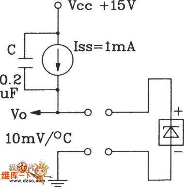
In a measuring temperature circuit diagram of TSV type temperature sensor using constant current, when we use constant current as load , the load current will not change,voltage drop of lead wire is a constant,so the ouput voltage will change according to10mV/℃.Usually control distant can reach up to thousand meters.
(View)
View full Circuit Diagram | Comments | Reading(469)
infrared remote control electric fan circuit
Published:2011/7/12 3:42:00 Author:Lena | Keyword: infrared, remote control, electric fan
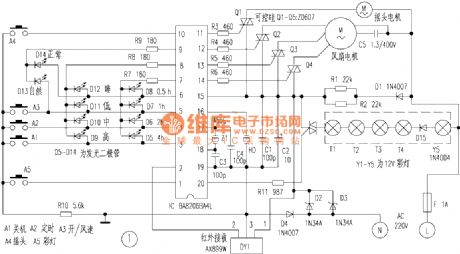
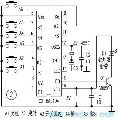
Here introduces a full function infrared remote control electric fan circuit, it has three functions include common wind, nature wind and sleep wind. It controls auto-shake, 0.5~7.5 hours timing off, and has a absolute night twilight spotlight, simple facture and easy usage.
Circuit principle: receiving circuit is shown as figure 1, we can know that the kernel part is a circuit brings togther infrared receiving amplifier, decoding, autocontrol, manual operation, LED emitting diode work state and timing off display set.
(View)
View full Circuit Diagram | Comments | Reading(1773)
wireless remote control code/encode circuit
Published:2011/7/12 7:11:00 Author:Lena | Keyword: wireless, remote control, code/encode
Wireless remote control receiving and transmitting switch circuits are mainly used to transfer data, the purpose is very wide. They are mainly used to centralized control of modern family multi-way power supply, intelligent residential district property management, anti-theft alarm system, wireless water tower control, wireless meter reading, navigation, aeromodelling and remote control measure etc multi-situation. Modern wireless remote control receiving and transmitting switch circuits have advanced circuits, and the manufacture technics have been transited to surface patch technics, integration and modularization from miscellaneous devices. This brings a small bulk, and the effect distant is from meters to few kilometers.
(View)
View full Circuit Diagram | Comments | Reading(467)
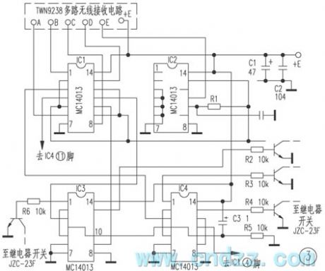
wireless remote control/touch switch circuit
Published:2011/7/12 7:01:00 Author:Lena | Keyword: wireless, remote control, touch switch
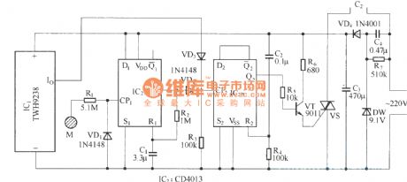
This remote control switch circuit can be used as far distance wireless remote control operation, can also control touch in near distance, the usage is very convenient. Composition principle is shown as the figure, it mainly composed by wireless remote control receiving component, touch control circuit, bistable states switch control circuit and power supply circuit. Remote control transmitting circuit uses finished product component TWH9236 which is not shown in figure.
(View)
View full Circuit Diagram | Comments | Reading(1068)
Automatic charging, power supply dual-use device circuit (1)
Published:2011/7/14 2:07:00 Author:TaoXi | Keyword: Automatic, charging, power supply, dual-use, device

The automatic charging, power supply dual-use device circuit is as shown in the figure 4-2. IC1 is the three-port voltage stabilizer LM317T, it forms the adjustable voltage stabilization power supply, the output voltage can be adjusted in the range of 1.25V-20V through RP1; IC2 is the CD4060, it is designed as one kind of 14-stage binary addition calculator/oscillator, the timer and pulse generator is composed of this calculator/oscillator and the external components. IC3 is the NE555, it forms the simple automatic charging circuit; IC4 is the sampling controller that is composed of the four-two input NAND gate CD4011 to control the conversion of the charging current.
After the battery is installed, it gives a positive pulse to the pin-12 of IC2 through C6, the IC2 starts to oscillate, the oscillation frequency is about 1.8Hz that is decided by the R6 and R7.
(View)
View full Circuit Diagram | Comments | Reading(734)
MYL3 lightning protection zinc oxide varistor appearance circuit
Published:2011/7/13 10:19:00 Author:Nancy | Keyword: lightning protection , zinc oxide varistor
View full Circuit Diagram | Comments | Reading(391)
| Pages:370/471 At 20361362363364365366367368369370371372373374375376377378379380Under 20 |
Circuit Categories
power supply circuit
Amplifier Circuit
Basic Circuit
LED and Light Circuit
Sensor Circuit
Signal Processing
Electrical Equipment Circuit
Control Circuit
Remote Control Circuit
A/D-D/A Converter Circuit
Audio Circuit
Measuring and Test Circuit
Communication Circuit
Computer-Related Circuit
555 Circuit
Automotive Circuit
Repairing Circuit