
Index 372
SG3525 DC Motor Driver Circuit
Published:2011/6/14 13:14:00 Author:Michel | Keyword: DC, Motor Driver Circuit
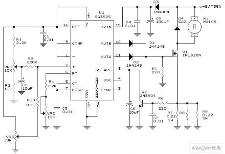
The picture is an accurate circuit which uses SG3525 ideal control DC motor.And illuminance,small heater's application circuits are changed into series of pulses.This circuit also can prevent overload, short-circuit and PWM (pulse width modulation) can be regualted among 0-100% and PWM frequency can be adjusted among 100Hz- 5KHZ.Work voltage range is +8 V-35V and minimum current consumption is about 35 mA.Maximum current can reach 6.5 A. Three potentiometers' functions as follows.VR1 determines minimum output voltage.VR3 sets maximum output voltage.VR2 sets output frequency.
Picture:SG3525 PWM DC Motor Controller Circuit (View)
View full Circuit Diagram | Comments | Reading(13013)
Electric Bridge Transducer Driver or Amplification Circuit of Constant Current Drive
Published:2011/6/14 13:13:00 Author:Michel | Keyword: Constant Current Drive, Electric Bridge Driver, Amplification Circuit
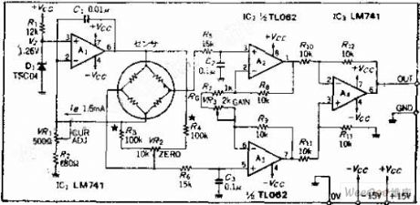
Circuit's Functions It's common that the strain gauge, magnetic resistance components, semiconductor pressure sensor etc. work in bridge way.This circuit uses MA constant current to unbalance the sensor and uses amplifier to receive.Sensor adopts diffused pressur sensor P-3000S-102G and its voltage range is 0~1KG/CM2.
Circuit's Work Principle OP amplifier A1 is constant current output circuit and the magnitude of the current is determined by reference voltage,VZ and sensing resistance.This circuit uses the maximum magnitude of the variable voltage or the OP amplifier output gets saturated,which makes the circuit unstable. (View)
View full Circuit Diagram | Comments | Reading(803)
MC68HC5Pl-Communication single-chip microcomputer integrated circuit diagram
Published:2011/7/10 2:44:00 Author:leo | Keyword: Communication, single-chip
MC68HC5PI is a kind of communication single-chip microcomputer integrated circuit made by Motorola which can be applied in wireless telephone and is used as control chip in cell phone.
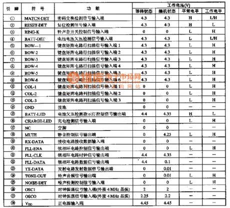
1.Function Feature:The integrated circuit MC68HC5PI is a type of chip which uses CMOSCPU as the core chip and has 16-bit input capturing and output comparing timers, serial peripheral interface, serial communication interface, 416OKB ROM, 24 double action I/O and can carry out the function of generating dual-tone multifrequency signals, coding data signals and pulsing dialing signals that that can be used to memory code information and so on.
2.Pin Function and dataMC68HC5PI is always used together with MC68HCO5C4(MC68HCO54P) as a microcomputer of the cell phone. All pins function and data of the integrated circuit are shown in the picture bellow. (View)
View full Circuit Diagram | Comments | Reading(445)
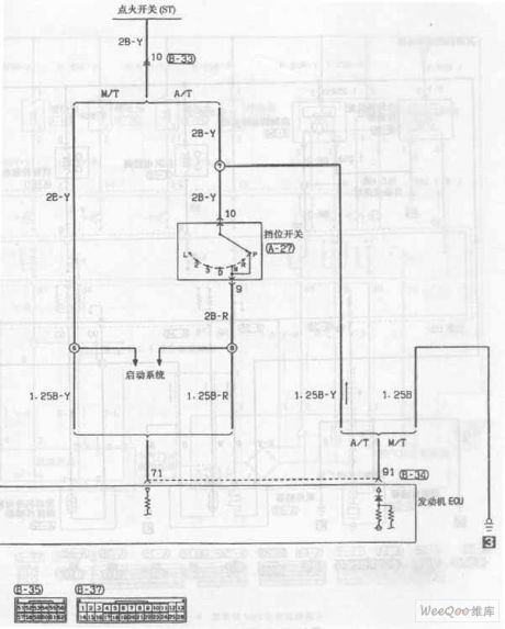
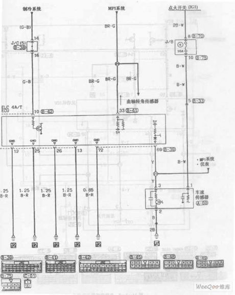
MPI System Launching Circuit One of Soueast Lioncel
Published:2011/7/8 21:46:00 Author:Michel | Keyword: Soueast Lioncel, MPI System Launching, Circuit One
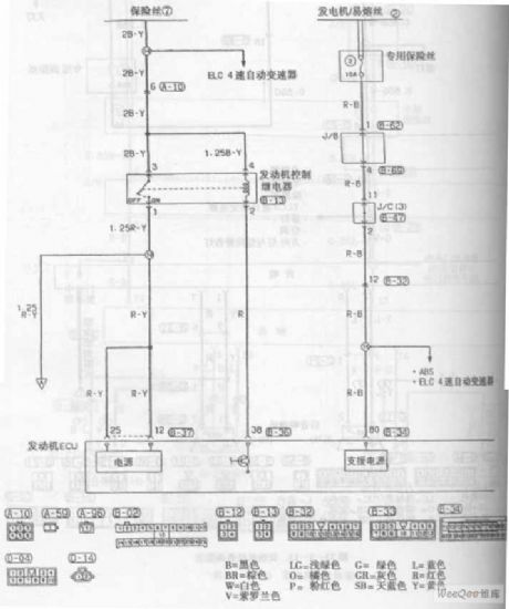
MPI System Launching Circuit of Soueast Lioncel (View)
View full Circuit Diagram | Comments | Reading(507)
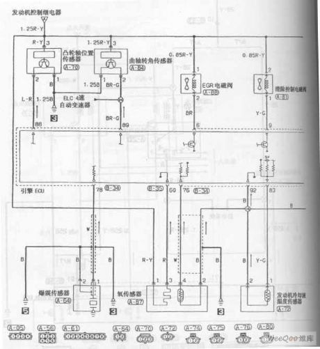
MPI System Launching Circuit Three of Soueast Lioncel
Published:2011/7/8 21:47:00 Author:Michel | Keyword: Soueast Lioncel, MPI System Launching, Circuit Three
MPI System Launching Circuit of Soueast Lioncel (View)
View full Circuit Diagram | Comments | Reading(478)
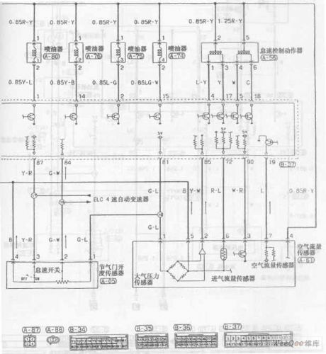
MPI System Launching Circuit Four of Soueast Lioncel
Published:2011/7/8 21:46:00 Author:Michel | Keyword: Soueast Lioncel, MPI System Launching, Circuit Four
MPI System Launching Circuit of Soueast Lioncel (View)
View full Circuit Diagram | Comments | Reading(540)
MPI System Launching Circuit Five of Soueast Lioncel
Published:2011/7/8 21:45:00 Author:Michel | Keyword: Soueast Lioncel, MPI System Launching, Circuit Five
MPI System Launching Circuit of Soueast Lioncel (View)
View full Circuit Diagram | Comments | Reading(563)
MPI System Launching Circuit Six of Soueast Lioncel
Published:2011/7/8 21:35:00 Author:Michel | Keyword: Soueast Lioncel , MPI System Launching, Circuit Six
MPI System Launching Circuit of Soueast Lioncel (View)
View full Circuit Diagram | Comments | Reading(504)
MPI System Launching Circuit Seven of Soueast Lioncel
Published:2011/7/8 21:36:00 Author:Michel | Keyword: Soueast Lioncel, MPI System Launching, Circuit Seven
MPI System Launching Circuit of Soueast Lioncel (View)
View full Circuit Diagram | Comments | Reading(518)
MPI System Launching Circuit Eight of Soueast Lioncel
Published:2011/7/8 21:37:00 Author:Michel | Keyword: Soueast Lioncel, MPI System Launching, Circuit Eight

MPI System Launching Circuit of Soueast Lioncel (View)
View full Circuit Diagram | Comments | Reading(532)
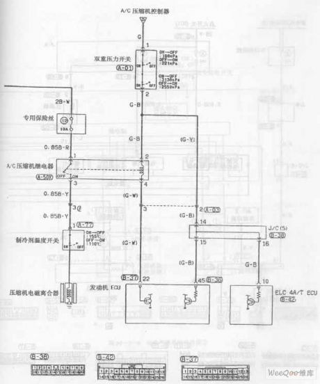
Engine Cooling System Circuit of Soueast Lioncel
Published:2011/7/8 21:39:00 Author:Michel | Keyword: Soueast Lioncel, Engine Cooling System, Circuit

Engine Cooling System Circuit of Soueast Lioncel (View)
View full Circuit Diagram | Comments | Reading(509)
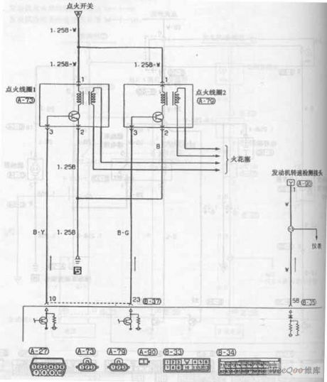
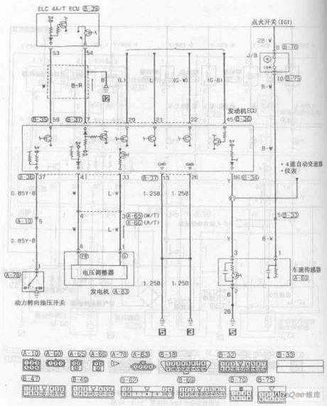
Engine Ignition System Circuit of Soueast Lioncel
Published:2011/7/8 21:38:00 Author:Michel | Keyword: Soueast Lioncel, Engine Ignition System, Circuit
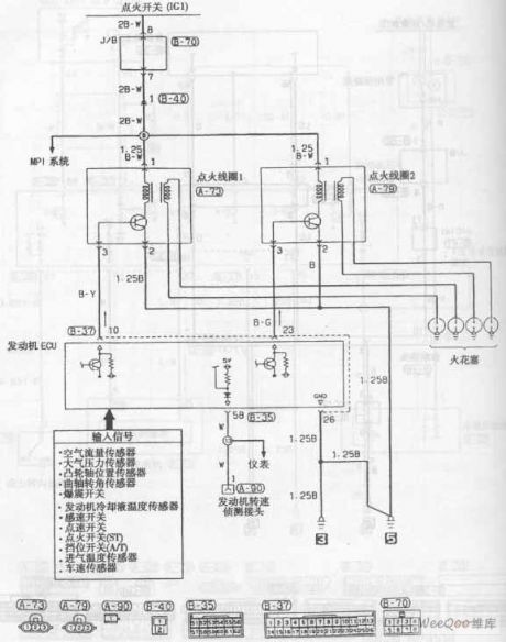
Engine Ignition System Circuit of Soueast Lioncel (View)
View full Circuit Diagram | Comments | Reading(573)
Automatic Transmission Circuit Four of Soueast Lioncel
Published:2011/7/8 21:43:00 Author:Michel | Keyword: Lingshuai Cars, Automatic Transmission, Circuit Four
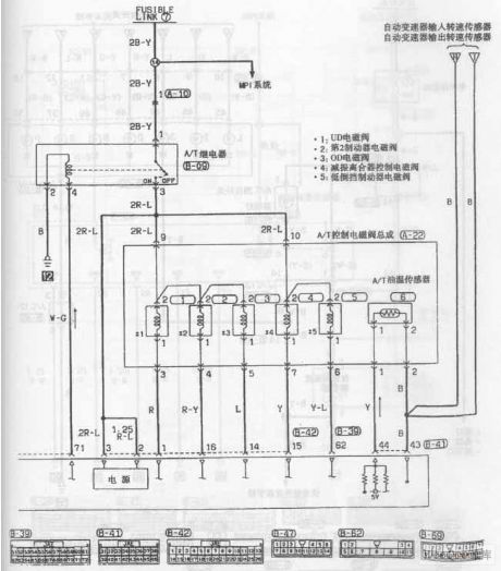
Automatic Transmission Circuit of Soueast Lioncel (View)
View full Circuit Diagram | Comments | Reading(568)
Automatic Transmission Circuit Three of Soueast Lioncel
Published:2011/7/8 21:41:00 Author:Michel | Keyword: Soueast Lioncel, Automatic Transmission, Circuit Three
Automatic Transmission Circuit of Soueast Lioncel (View)
View full Circuit Diagram | Comments | Reading(576)
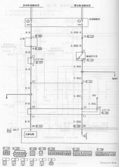
Automatic Transmission Circuit Six of Soueast Lioncel
Published:2011/7/8 21:44:00 Author:Michel | Keyword: Soueast Lioncel, Automatic Transmission, Circuit Six
Automatic Transmission Circuit of Soueast Lioncel (View)
View full Circuit Diagram | Comments | Reading(523)
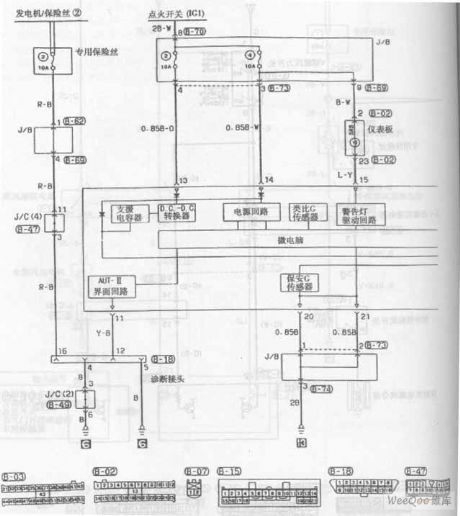
Air Bag System Circuit Two of Soueast Lioncel
Published:2011/7/9 23:09:00 Author:Michel | Keyword: Soueast Lioncel, Air Bag System, Circuit Two
Air Bag System Circuit of Soueast Lioncel (View)
View full Circuit Diagram | Comments | Reading(674)
Air Bag System Circuit One of Soueast Lioncel
Published:2011/7/9 23:09:00 Author:Michel | Keyword: Soueast Lioncel, Air Bag System, Circuit One
Air Bag System Circuit of Soueast Lioncel (View)
View full Circuit Diagram | Comments | Reading(708)
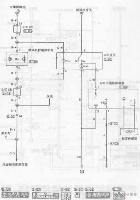
Air-conditioning Circuit Three of Soueast Lioncel
Published:2011/7/9 23:10:00 Author:Michel | Keyword: Soueast Lioncel, Air-conditioning Circuit Three
Air-conditioning Circuit of Soueast Lioncel (View)
View full Circuit Diagram | Comments | Reading(614)
Push-pull Type DC/DC Converter Circuit
Published:2011/7/7 16:20:00 Author:Michel | Keyword: Push-pull Type, DC/DC, Converter Circuit
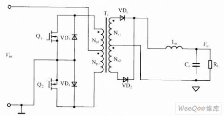
The push-pull type DC/DC converter circuit is shown as above.Among them,transformer T1 acts as isolation and energy transmission.When switch tube Q1 turns on,transformer T1's windings works and it couples with vice side Ns1 winding.When switch tube Q1 turns off,Np1 releases energy to Ns1 and vice versa.The vice edge of rectifier circuit on output end is composed of flow inductor Lo and VD1, VD2.In the circuit design,both ends of switch tube should set RC absorbing circuit to the peak surge which is produced when the switch tube turns off.
Picture:Push-pull Type DC/DC Converter Circuit
(View)
View full Circuit Diagram | Comments | Reading(4118)
LX5104 Infrared Coding Circuit
Published:2011/7/1 8:03:00 Author:Michel | Keyword: Infrared, Coding Circuit
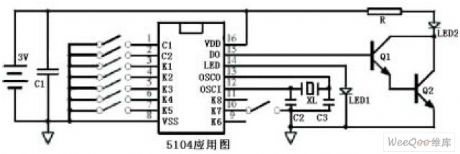
LX5104 Infrared Coding Circuit (View)
View full Circuit Diagram | Comments | Reading(974)
| Pages:372/471 At 20361362363364365366367368369370371372373374375376377378379380Under 20 |
Circuit Categories
power supply circuit
Amplifier Circuit
Basic Circuit
LED and Light Circuit
Sensor Circuit
Signal Processing
Electrical Equipment Circuit
Control Circuit
Remote Control Circuit
A/D-D/A Converter Circuit
Audio Circuit
Measuring and Test Circuit
Communication Circuit
Computer-Related Circuit
555 Circuit
Automotive Circuit
Repairing Circuit