
Index 377
μA723/723C series of regulator, main features and pin of DC-DC circuit and power supply monitor
Published:2011/7/9 23:57:00 Author:Lucas | Keyword: regulator, main features , pin , DC-DC circuit, power supply monitor
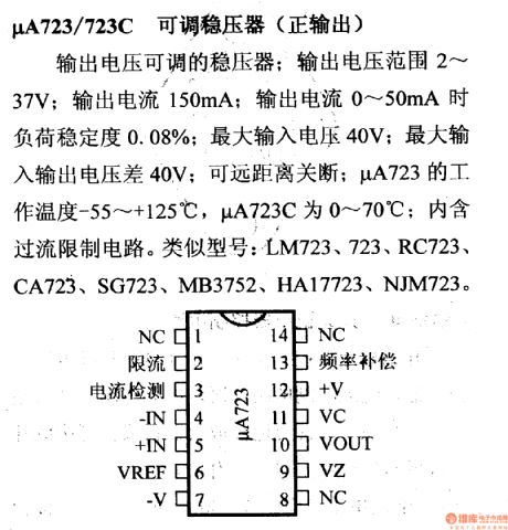
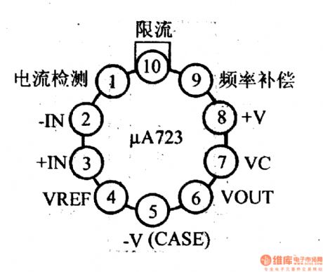
μA723/723C adjustable regulator( positive output)
It's the regulator with adjustable output voltage; output voltage range is 2 ~ 37V, output current is 150mA; when current output is between 0 ~ 50mA, the load stability is 0.08%; the maximum input voltage is 40V; maximum input voltage difference is 40V; it can be turned off in long distance; μA723 operating temperature is -55 ~ +125 ℃, μA723C is 0 ~ 70 ℃; it includes over-current limiting circuit. Similar models: LM723, 723, RC723, CA723, SG723, MB723, HA17723, NJM723.
(View)
View full Circuit Diagram | Comments | Reading(1306)
W4962 switch regulator, main features and pin of DC-DC circuit and power supply monitor
Published:2011/7/10 1:54:00 Author:Lucas | Keyword: switch regulator, main features , pin , DC-DC circuit , power supply monitor
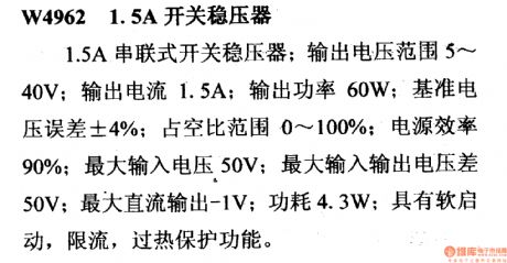
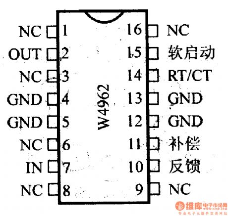
W4962 1.5A switch regulator
It is the 1.5A tandem switching regulator; output voltage range is 5 ~ 40V; output Current is 1.5A; output power is 60W; reference voltage is ± 4%; duty cycle range is 0 to 100%; power efficiency is 90%; maximum input voltage is 50V ; maximum difference between input and output voltage is 50V; maximum DC output is -1V; power is 4.3W; it has the functions of soft start, current limit, thermal protection.
(View)
View full Circuit Diagram | Comments | Reading(517)
AC RMS / DC converter circuit composed of AD533
Published:2011/7/6 8:01:00 Author:Lucas | Keyword: AC RMS converter, DC converter
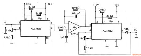
This is also circuit which could operate the multiplier AD533 and change AC RMS into the DC voltage. In the circuit, AD533 (1) makes the square operation on the input AC voltage instantaneous value, and its output is integrated by integrator Al, and square operated by AD533 (2), and AD533 (2)'s output is the the average value of input AC signal.
(View)
View full Circuit Diagram | Comments | Reading(2076)
AC RMS / DC converter circuit composed of AD536J
Published:2011/7/6 7:52:00 Author:Lucas | Keyword: AC RMS converter , DC converter
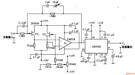
This is an operational AC RMS / DC conversion circuit, which could change AC RMS into the operation of DC voltage. AD536J input impedance is lower with only about 16kΩ, so the application should access the input buffer. In the figure, Al (LM318) is the buffer, the input impedance can be increased to lMΩ. Cl is the frequency compensation capacitor, and C2 is high-frequency compensation capacitor, which can change its capacity to improve the frequency characteristics.
(View)
View full Circuit Diagram | Comments | Reading(3398)
AC / DC conversion circuit composed of LM3O1A
Published:2011/7/6 19:13:00 Author:Lucas | Keyword: AC conversion, DC conversion
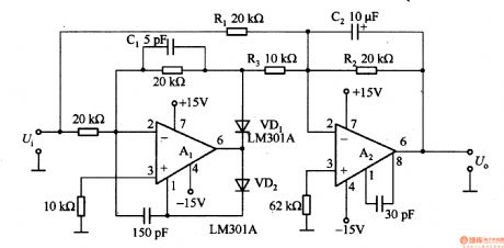
Operational amplifier Al is connected in series in the feedback circuit to be used as the inverting amplifier, for negative input signal, VDl is stopped and not related to circuit, so Al output is 0V. A2 works as the gain of -R2Ui/Rl according to the resistance of Rl, R2. For positive input signals, A2 adds the signal from R3 and Rl. If R3 = Rl / 2, the U. = UiR2/Rl. In order to get the output voltage which is equal to the average of the input voltage, then C2 and R2 provide low-pass filter characteristics for A2.
(View)
View full Circuit Diagram | Comments | Reading(938)
RMS / DC converter circuit for measuring AC voltage in digital multimeter
Published:2011/7/6 19:46:00 Author:Lucas | Keyword: RMS converter, DC converter measuring AC voltage converter digital multimeter
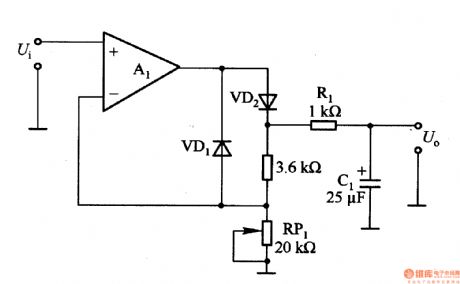
For 2V rms sinusoidal input Ui, in order to get 2V DC output voltage U. , the positive half-cycle of Al is used as a noninverting amplifier with gain work, and RR1 is used to change the gain of A1; for 2V AC RMS input voltage, RR1 transfer the output DC voltage to 2V. Rl and Cl form the low-pass filter to make the output voltage ripple small and smooth.
(View)
View full Circuit Diagram | Comments | Reading(11212)
High-frequency RMS / DC converter circuit composed of AD8361
Published:2011/7/6 19:40:00 Author:Lucas | Keyword: High-frequency, RMS converter , DC converter
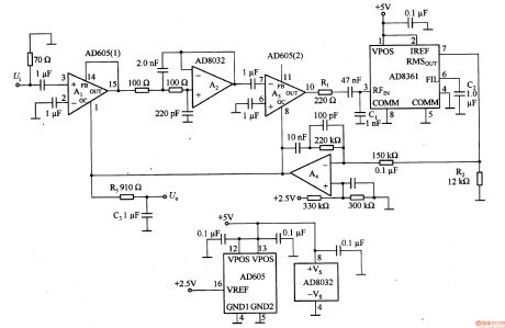
The circuit has an accurate high-frequency variable gain amplifier (VGA) (Al and A3) and high-speed RMS detector, the users don't need to change the amplifier's gain. This circuit can be used to measure complex high-frequency waveform RMS in a wide range. In the circuit, VGA is connected in the signal path in front of RMS detector as an integral part of automatic gain (AGC) loop. When the difference of tuning point is accumulated into a control voltage, it will make RMS detector output remain constant.
(View)
View full Circuit Diagram | Comments | Reading(2839)
Frequency / voltage conversion circuit composed of TC9142P
Published:2011/7/7 22:22:00 Author:Lucas | Keyword: Frequency conversion, voltage conversion
In the circuit, the input frequency fi is the digital signal, and the output voltage UO is analog signal. The circuit's frequency / voltage conversion circuit uses 8-bit D / A converter TC9142P, and the difference with the RC integrator is the change the DC level converted from frequency, and the DC conversion has high efficiency, in particular, when it constitutes the servo system, it has fast response, so it is widely used in high-precision motor control system. In the circuit, operational amplifier Al is used as buffer. (View)
View full Circuit Diagram | Comments | Reading(488)
Frequency / voltage conversion circuit composed of SN74121
Published:2011/7/7 4:16:00 Author:Lucas | Keyword: Frequency conversion, voltage conversion
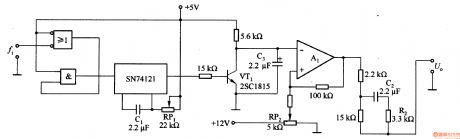
In the circuit, the time constant is decided by the Cl and R (RP1), R2 and C2 are used for phase compensation in order to improve system performance.
(View)
View full Circuit Diagram | Comments | Reading(2196)
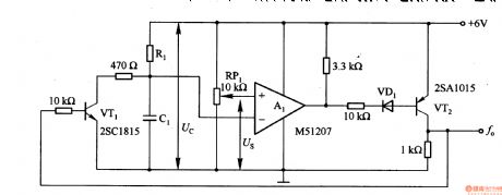
Frequency / voltage conversion circuit composed of transistor
Published:2011/7/6 20:07:00 Author:Lucas | Keyword: Frequency conversion, voltage conversion, transistor
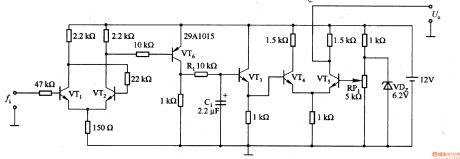
In the Figure 1-19 (a), the VTl and VT2 form the Schmidt circuit to shape the input waveform; Rl and C1 form the integration circuit; VT3 is the buffer circuit; the VT4 and VT5 form the amplifier circuit. The main features of the circuit is that it has high noise immunity, adjustable signal level and circuit constants, and it is the basic frequency / voltage conversion circuit. In the Figure 1-19 (b), the output mostly uses operational amplifier, and the output part uses the frequency / voltage conversion circuit composed of transistors.
(View)
View full Circuit Diagram | Comments | Reading(1905)
Frequency / voltage conversion circuit composed of analog switch
Published:2011/7/6 20:02:00 Author:Lucas | Keyword: Frequency conversion , voltage conversion , analog switch
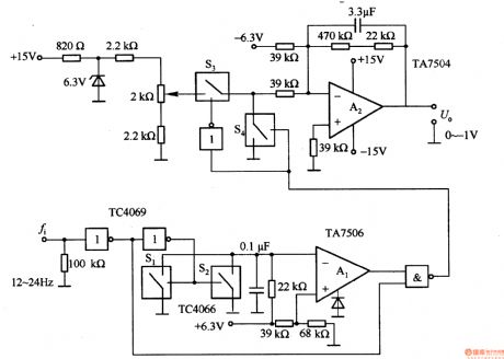
The circuit has improved the monostable circuit and the switching circuit with higher precision conversion, and it can switch 12 to 24Hz frequency signal to 0 to -lV voltage signal.
(View)
View full Circuit Diagram | Comments | Reading(574)
the internal equivalent circuit of NJM4200 multiplier
Published:2011/7/10 3:44:00 Author:chopper | Keyword: internal, equivalent circuit, multiplier
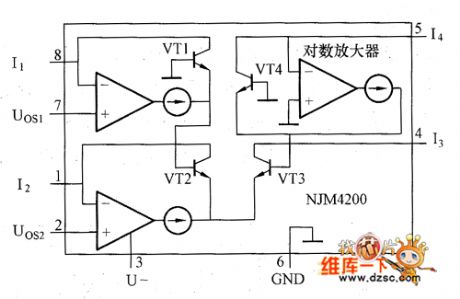
Figure shows the internal equivalent circuit of NJM4200, and the chip includes logarithmic amplifiers and so on. Function of the Logarithmic amplifier is to use the logarithmic relationship of voltage and current of PN,and add and subtract logarithm of current,then do the logarithmic transformation for the result.The transition function of NJM4200 is I3=(I1I2)/I4,and the input/output range is 1μA~1mA.NJM4200 may be damaged when the input current is more than 5mA,while the frequency characteristics is poor when small signal level is in use,therefore, we should use it near the full-scale as possible as we can.
(View)
View full Circuit Diagram | Comments | Reading(695)
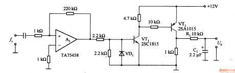
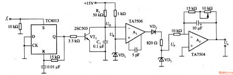
Frequency / voltage conversion circuit composed of TA7506
Published:2011/7/6 20:00:00 Author:Lucas | Keyword: Frequency conversion, voltage conversion
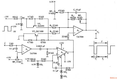
Al is the waveform shaping circuit, and A2 is the monostable multivibrator,then it gets a constant pulse width T2. VT1, VT2 and A3 constitute a frequency / voltage conversion circuit. In the T2 period, VTl turns on and integrates -U (REF) voltage; in the T1 period, VTl ends and VT2 conduction, the integrator A3 input voltage is OV. The C5, R3 and RP2 form low-pass filter, so A3 output is DC voltage. Adjusting the value of RP3 make fi = 12Hz, U. = OV; adjusting RP2 value make fi = 24Hz, U. = LV.
(View)
View full Circuit Diagram | Comments | Reading(687)
Pulse width / voltage conversion circuit composed of μPC157
Published:2011/7/7 22:17:00 Author:Lucas | Keyword: Pulse width conversion, voltage conversion
After the input end is addedthe negative pulse, A1 starts integrate. The input pulse inversion is in high level, to sample and keep the output of the integrator. After sampling, the integrator resets. Repeat this operation, we can obtain the output pulse width which is proportional to the output voltage.
(View)
View full Circuit Diagram | Comments | Reading(754)
Voltage / frequency conversion circuit composed of TC4013
Published:2011/7/7 22:12:00 Author:Lucas | Keyword: Voltage conversion, frequency conversion
It can switch 0-100Hz input frequency to 0 -l0V output voltage. In the circuit, TC4013 is a monostable multivibrator, which could shape and amplify input pulse, and the input pulse width is 1OOμs. TC4013 could trigger VTl to turn on, when the input voltage of of comparator Al UQ <UR, its output is positive. VTl is only conducted in 10Oμs, then returned to the cut-off state, and capacitor Cl starts charging. When the charging voltage of C1 is up to UQ> UR, Al output becomes negative.
(View)
View full Circuit Diagram | Comments | Reading(2824)
DC Voltage Regulation Circuit of Single Pipe Amplifier Transistor
Published:2011/7/7 22:51:00 Author:Michel | Keyword: Single Pipe, Amplifier Transist, DC, Voltage Regulation Circuit
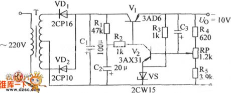
The DC voltage regulation circuit of single pipe amplifier transistor is shown as above.Welome to download the ciruit and the circuit is from www.dzsc.com. (View)
View full Circuit Diagram | Comments | Reading(502)
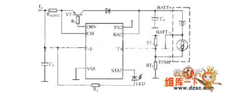
The basic application circuit of AAT3680
Published:2011/7/10 18:51:00 Author:TaoXi | Keyword: basic application
View full Circuit Diagram | Comments | Reading(476)
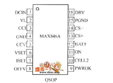
Pin arrangement circuit of the MAX846A
Published:2011/7/10 19:06:00 Author:TaoXi | Keyword: Pin, arrangement
View full Circuit Diagram | Comments | Reading(509)
5V/10A 100khz choking coil communication device circuit uses the SIPMOS transistor
Published:2011/7/10 19:01:00 Author:TaoXi | Keyword: 5V/10A, 100khz, choking coil, communication device, SIPMOS transistor
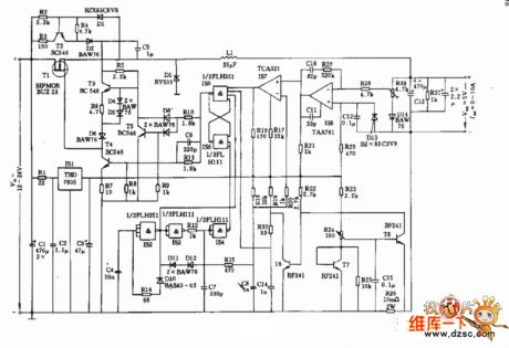
Figure:5V/10A 100khz choking coil communication device circuit uses the SIPMOS transistor
(View)
View full Circuit Diagram | Comments | Reading(512)
The interface circuit of the AD7714 and MCS-51 series single-chip microcomputer
Published:2011/7/8 4:35:00 Author:Christina | Keyword: interface circuit, single-chip microcomputer
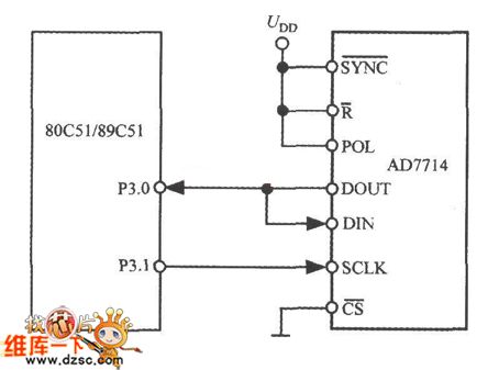
The 3-wire interface of the AD7714 can be equipped with a variety kinds of microcontrollers (contains the microcontroller or the microprocessor). The 3-wire serial interface can be used in the isolation system, and it can reduce the number of the optical coupler to minimum. The interface circuit of the AD7714 and 80C51 (or the 87C51, 89C51) is as shown in the figure. The 80C51 only use two interface leads (P3.0,P3.1). At this time, the non-bit DRDY of the monitoring configuration register can be used to determine the update time of the data register.
(View)
View full Circuit Diagram | Comments | Reading(480)
| Pages:377/471 At 20361362363364365366367368369370371372373374375376377378379380Under 20 |
Circuit Categories
power supply circuit
Amplifier Circuit
Basic Circuit
LED and Light Circuit
Sensor Circuit
Signal Processing
Electrical Equipment Circuit
Control Circuit
Remote Control Circuit
A/D-D/A Converter Circuit
Audio Circuit
Measuring and Test Circuit
Communication Circuit
Computer-Related Circuit
555 Circuit
Automotive Circuit
Repairing Circuit