
Index 379
Three-phase motor contactor auxiliary contact interlock switching circuit
Published:2011/7/8 6:33:00 Author:Lucas | Keyword: Three-phase , motor contactor , auxiliary contact , interlock switching
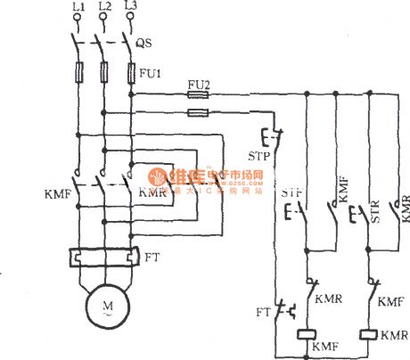
The circuit shown as the chart uses two AC contactors KMF and KMR. KMF is used for forward, KMR is used for reversal. As the main contact wiring phase sequence of AC contactor is different, when the two contacts are at work, the motor turning is opposite. Because of this, the operation dose not allow KMF and KMR to be pulled at the same time. To this point, in the forward and reverse control circuits, each circuit is stringed into the normally closed contact of the other one. Contactor self-protection auxiliary contacts KMF, KMR are increased in the circuit.
(View)
View full Circuit Diagram | Comments | Reading(7829)
Three-phase motor operation conversion circuit
Published:2011/7/8 6:45:00 Author:Lucas | Keyword: Three-phase , motor operation , conversion circuit
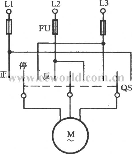
In order to change the turning of three-phase motor, it only needs to switch any two-phase wiring of three-phase power. In the occasion which is often needed to switch motor running direction, it can reach the goal by one double-throw plastic cover knife switch QS connected as shown. Methods of operation: normal knife switch handle is often in the center stop position; when it needs to forward, the knife switch handle could be pulled to the positive ; In order to change direction, that is, the swicth is pulled to the stop , then anti after the motor being stable.
(View)
View full Circuit Diagram | Comments | Reading(1053)
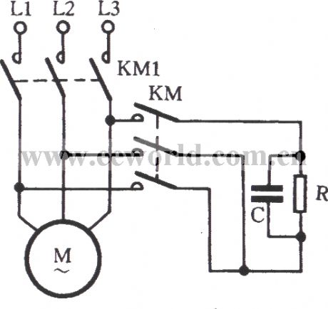
Three-phase motor and self-motivation - short braking circuit
Published:2011/7/9 6:13:00 Author:Lucas | Keyword: Three-phase motor, self-motivation - short, braking circuit
View full Circuit Diagram | Comments | Reading(645)
Three-phase motor automatic limiting reversing circuit
Published:2011/7/9 7:47:00 Author:Lucas | Keyword: Three-phase motor, automatic limiting , reversing circuit
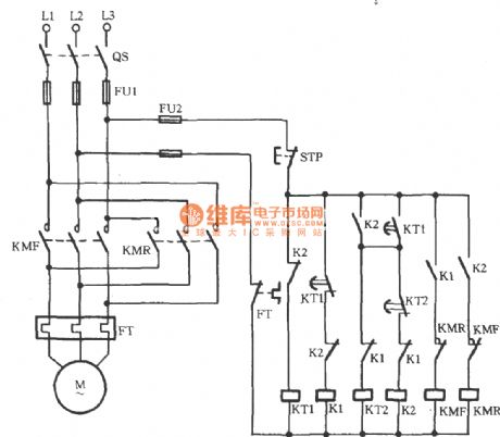
In the circuit shown as the chart, KT1, KT2 are the time relays. After closing the main switch QS, K1 and KMF pulls in, then the motor runs forward, and KT1 starts to time. When the time of KT1 arrives, it automatically disconnects, and K1 coil loses power, and KMF releases, then the motor stops; At the same time, the normally open contacts of KT1 are closed, and coil K2 pulls in, KMR coil gets electric to make motor run reversely, then KT2 starts to time. When the time of KT2 arrives, its normally contact KT2 is closed, and K2 coil loses power to make KMR release, then the motor stops. K2's loss of power could make its the normally closed contact restore normally closed state, then KT1, K1 work make the motor run forward.
(View)
View full Circuit Diagram | Comments | Reading(3244)
Automatic Transmission Circuit Eight of Southest Lingshuai Cars
Published:2011/7/7 21:28:00 Author:Michel | Keyword: Lingshuai Cars, Automatic Transmission, Circuit Eight
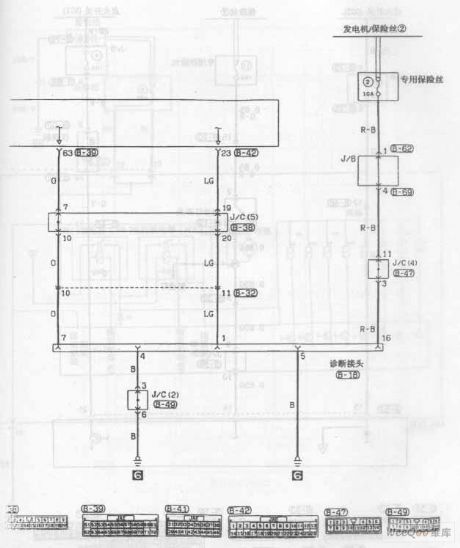
Automatic Transmission Circuit of Southest Lingshuai Cars (View)
View full Circuit Diagram | Comments | Reading(599)
Voltage / frequency and frequency / voltage conversion circuit composed of VFC320
Published:2011/7/6 19:28:00 Author:Lucas | Keyword: Voltage / frequency conversion, frequency / voltage conversion
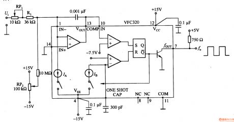
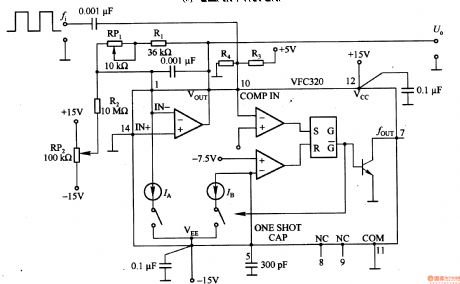
Figure 1-22 (a) shows the circuit which could convert 0-+lOV input voltage Ui into the pulse with 0 -1OOkHz output frequency, and pin 7 of VFC320 is connected a resistor to directly connect to standard logic. Figure 1-22 (b) shows the the circuit which could convert the pulse with 0-100KHz input frequency into 0-+lOV output voltage UO. If the signal counter of CPU is for voltage / frequency converter output, then it can be used as the A / D converter with strong anti-noise ability; If the frequency / voltage converter is used in combination with the optical chopper, the motor speed can form analog voltage conversion circuit.
(View)
View full Circuit Diagram | Comments | Reading(2200)
RMS / DC converter circuit composed of AD736
Published:2011/7/6 19:33:00 Author:Lucas | Keyword: RMS converter, DC converter
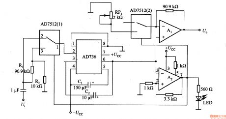
In the circuit, AD736 rms converter chip is the divice with full-scale voltage in lV, and A2 comparison amplifier will automatically zoom full-scale input voltage to the lOV. When rms is beyond the range of valid values in the second-rate conversion, A2's output control analog switch AD7512 (1) is connected to AD736 input attenuator. At the same time, it is connected to the output buffer amplifier A1 to improve the gain and stabilize the output voltage. When the input signal of AD736 in the range of 0.1 to 1V RMS conversion, AD7512 (1) analog switches 1 and 2 are connected.
(View)
View full Circuit Diagram | Comments | Reading(3370)
220V power supply LED lamp driver circuit
Published:2011/7/8 2:41:00 Author:Fiona | Keyword: 220V power supply, LED lamp driver
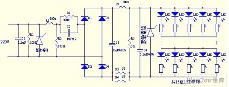
In the circuit,C1,R1,piezoresistor,L1,R2 form the primary power supply filter circuit,it can be able to filter the input instant high voltage,C2,R2 form step-down circuit,C3,C4,L2 and piezoresistor form the filter circuit after rectifying. This circuit uses a dual filter circuit,it can effectively protect the LED not be breakdown and damage by instant high voltage.
(View)
View full Circuit Diagram | Comments | Reading(6242)
wireless remote control/touch dimmer circuit(RCM1A/RCM1B)
Published:2011/6/20 8:10:00 Author:Lena | Keyword: wireless, remote control, touch dimmer
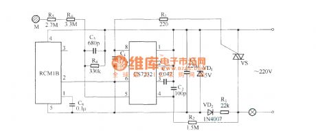
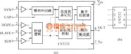
Wireless remote control/touch dimmer circuit is an incandescent lamp dimmer switch with wireless remote control component RCM1A/RCM1B and touch dimmer integrated circuit CS7232 as the core. It can be used to control droplight, reading lamp and wall lamp etc, provided with small bulk, convenient usage, stable and reliable work characteristics.CS7232 is a CMOS type integrated circuit used to control incandescent lamp dimmer. It can control breakover of bidirectional thyristor to realize lamp brightness control, provided with low power loss, multi purpose , high sensitivity etc characteristics.
(View)
View full Circuit Diagram | Comments | Reading(1173)
TMP47C400RN Microwave/Oven Monolithic Micro Computer Control Integrated Circuit Diagram
Published:2011/7/3 1:56:00 Author:Vicky | Keyword: Microwave, Oven , Monolithic Micro Computer Control
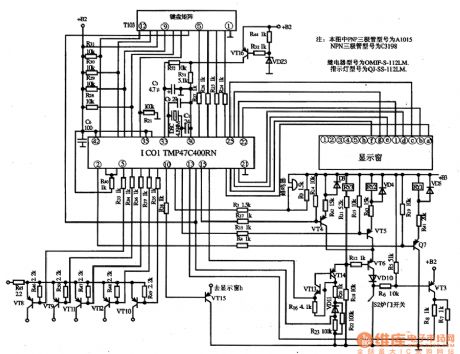
Picture 1 is the typical applied circuit diagram of TMP47C4OORN integrated circuit.
TMP47C400RN is a chip specially designed by Japanese Toshiba Corporation for microwave/oven.
1 functions and features
TMP47C400RN integrated circuit includes keyboard matrix circuit, clock oscillator circuit, motion circuit, reset circuit, microwave control circuit, oven light control circuit and other accessory circuits.
2 pin functions and datum
TMP47C400RN integrated circuit adopts 42 pins in biserial package.
3 typical applied picture
Typical applied circuit of IC TMP47C400RN is shown in the above picture.
Note: When the microwave or oven does not work, you should first check if the 12V AC in the pin 42 of the IC TMP47C4OORN is normal or not, then check the reset signal in the pin 33 (it presents low level at the moment of starting up, and high level during normal work) and the clock oscillating signal pins 31&32.
(View)
View full Circuit Diagram | Comments | Reading(4513)
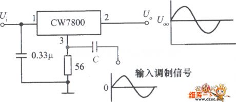
Power modulator circuit composed of the integrated voltage stabilizer CW7800
Published:2011/7/7 2:56:00 Author:Christina | Keyword: Power modulator, integrated voltage stabilizer
View full Circuit Diagram | Comments | Reading(440)
Typical application circuit of the LM/LT multi-functional switch integrated regulator
Published:2011/7/7 3:10:00 Author:Christina | Keyword: Typical application, LM/LT, multi-functional, switch, integrated regulator
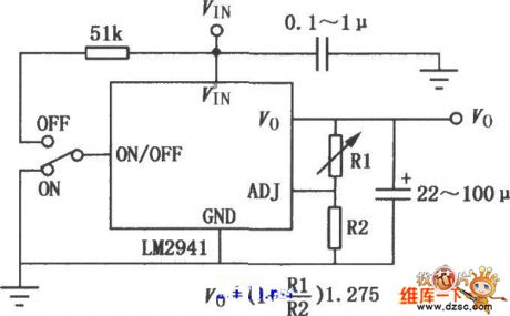
Figure:Typical application circuit of the LM/LT multi-functional switch integrated regulator
(View)
View full Circuit Diagram | Comments | Reading(586)
RMS level measuring instrument circuit composed of the AD8362
Published:2011/7/7 3:24:00 Author:Christina | Keyword: RMS level, measuring instrument
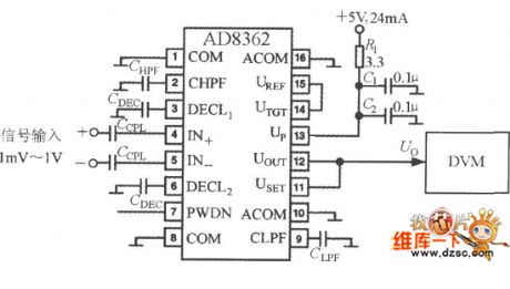
The RMS level measuring instrument circuit which is composed of the AD8362 is as shown in the figure, the output voltage of AD8362 is added to the digital voltmeter (DVM) directly. You should notice that the reading of DVM is proportional with the logarithm of the measured RMS voltage, so it is the voltage level measuring instrument, the display unit is dBv. When you are measuring the radio-frequency signal with high input frequency, you must use the measures as follow: the first is that you need to add the decoupling capacitor to the input port, the second is that you need to shorten the length of the input signal leads, the decoupling capacitor leads and the ground leads. The decoupling network of the +5V power supply is composed of the R1, C1 and C2.
(View)
View full Circuit Diagram | Comments | Reading(650)
TOP22-227 principle circuit
Published:2011/7/7 20:18:00 Author:Christina | Keyword: principle
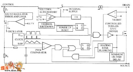
Set the TOP smart power switch as the example, the principle circuit of the TOP22X series devices are as shown in the figure. The TOP22X switch only has three leads, in addition to the drain lead and the feedback control lead of the power switch, there is a feedback control lead. The operating frequency is 100 kHz, the operating mode is the voltage type PWM. The output voltage is detected, compared and amplified, then it changes into the current signal and adds to the feedback control lead, the internal RE resistance changes the current signal into the voltage signal to compare with the triangular wave, so it changes the pulse width to realize PWM modulation.
TOP22-227 principle circuit (View)
View full Circuit Diagram | Comments | Reading(503)
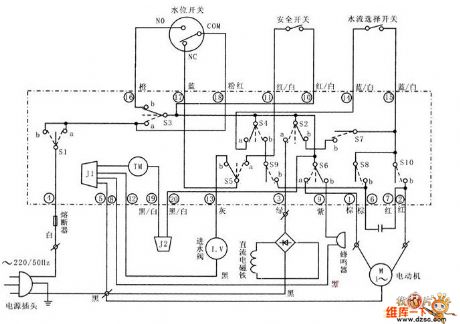
Panasonic NA1900 washing machine circuit
Published:2011/7/7 20:20:00 Author:Christina | Keyword: Panasonic, washing machine
The Panasonic NA1900 washing machine circuit is as shown in the figure:
(View)
View full Circuit Diagram | Comments | Reading(4138)
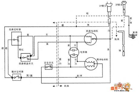
Xiaoshentong XQB20-A washing machine circuit principle diagram
Published:2011/7/7 20:25:00 Author:Christina | Keyword: Xiaoshentong, XQB20-A, washing machine, principle diagram
The Xiaoshentong XQB20-A washing machine circuit principle diagram is as shown in the figure:
(View)
View full Circuit Diagram | Comments | Reading(696)
TA8173 surround sound control integrated circuit
Published:2011/7/6 5:57:00 Author:chopper | Keyword: surround sound, control integrated circuit

TA8173AP is a surround sound control integrated circuit produced by Company Toshiba ,and it is applied to karaoke, TV sound system.1.The inner circuit and typical application circuit of TA8173APThe inner circuit and typical application circuit of TA8173AP integrated package are shown as picture 1.
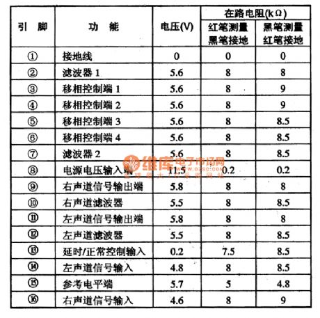
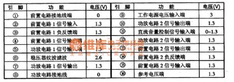
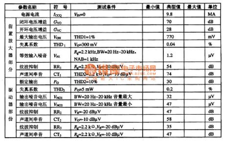
2.function and data of pins of TA8173APTA8173AP integrated circuit adopts dual inline 16 pinned package,and its function and data of pins are shown as chart 1.
(View)
View full Circuit Diagram | Comments | Reading(2611)
Power measurement system demodulating circuit
Published:2011/7/6 20:55:00 Author:Christina | Keyword: Power measurement system, demodulating circuit
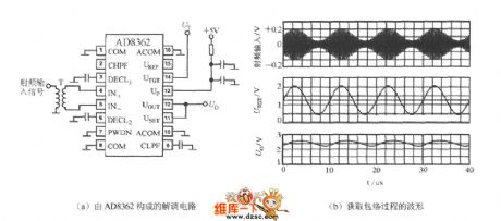
You can use the AD8362's UTGT port to form the demodulating circuit, this circuit can take out the envelope of the RF AM wave and revert it into the intermediate and low frequency signals. The demodulation circuit and the envelope process are as shown in figure (a) and (b). Here we suppose the input signal is the modulated 100kHz sine wave, the carrier frequency is 100 MHz. If you connect the 1.25V (average) voltage VT to the pin-14, the output voltage of pin-12 is the modulated 100kHz sine wave signal.
(View)
View full Circuit Diagram | Comments | Reading(2417)
TA8119 monolithic stereo playback integrated circuit
Published:2011/7/5 1:13:00 Author:chopper | Keyword: monolithic, stereo, playback, integrated circuit
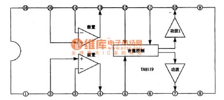
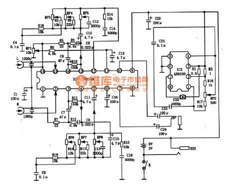
TA8119 is a monolithic playback integrated circuit produced by Japanese company TOSHIBA,and it is applied to mini cassette players.1.inner circuit and function of pins TA8119 integrated package includes playback circuit whose golden part is used in 3V stereo earplugs type cassette.The preamplifier and headphones are independent, and loop gain is 30db and it includes ripple wave as well as filtering wave and extensible dc voltage input level.The inner circuit of TA8119 integrated package is shown as picture 1.This IC has two encapsulation methods.
(View)
View full Circuit Diagram | Comments | Reading(1701)
TA8111AP monolithic stereo playback integrated circuit
Published:2011/7/4 23:42:00 Author:chopper | Keyword: monolithic, stereo, playback integrated circuit
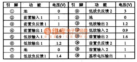
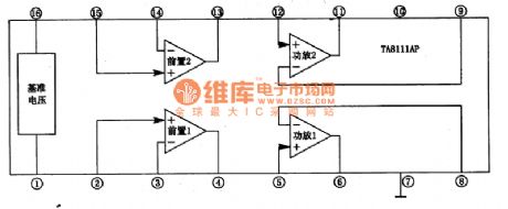
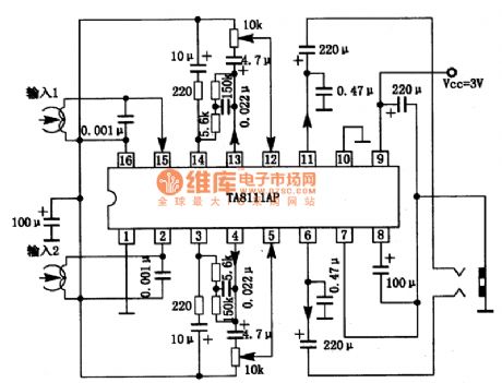
TA8111AP is a monolithic playback integrated circuit produced by Company TOSHIBA,and it is applied to mini acoustic system like low-voltage walkman and so on.1.inner circuit and function of pins The inner circuit of TA8111AP integrated package includes two same preposing equilibrium amplifier circuits,two same power amplifier circuits. This IC adopts dual inline 16 pinned package.Its function and data of pins are shown as chart 1.
(View)
View full Circuit Diagram | Comments | Reading(1183)
| Pages:379/471 At 20361362363364365366367368369370371372373374375376377378379380Under 20 |
Circuit Categories
power supply circuit
Amplifier Circuit
Basic Circuit
LED and Light Circuit
Sensor Circuit
Signal Processing
Electrical Equipment Circuit
Control Circuit
Remote Control Circuit
A/D-D/A Converter Circuit
Audio Circuit
Measuring and Test Circuit
Communication Circuit
Computer-Related Circuit
555 Circuit
Automotive Circuit
Repairing Circuit