Filter Circuit
DZW75-48/5050II high frequency rectifier filter circuit
Published:2011/12/4 20:45:00 Author:May | Keyword: high frequency reetifier, filter | From:SeekIC
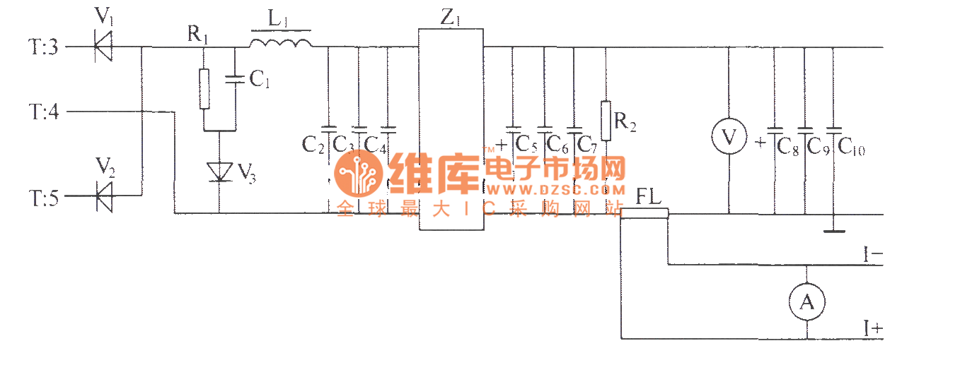
Alternating positive and negative pulse voltage of high-frequency transformer T's secondary induction is rectified by the full-wave rectifier composed of high-power high frequency switching diodes V1,V2, then it is smoothed filtered by L filter composed of inductor and capacitors C2, C3, C4 and Z1 power filter, then it gets 48V volts d.c. output with met the index high and low frequency noise requirements at output end. Impulse width determines the height of output voltage directly. Impulse width is wide, and output voltage is high, impulse width is narrow, output voltage is low. The output end is connected a voltmeter in order to measure display output volts d.c. R2 is leak resistor, and FL is current divider.
Reprinted Url Of This Article:
http://www.seekic.com/circuit_diagram/Basic_Circuit/Filter_Circuit/DZW75_48_5050II_high_frequency_rectifier_filter_circuit.html
Print this Page | Comments | Reading(3)

Article Categories
power supply circuit
Amplifier Circuit
Basic Circuit
LED and Light Circuit
Sensor Circuit
Signal Processing
Electrical Equipment Circuit
Control Circuit
Remote Control Circuit
A/D-D/A Converter Circuit
Audio Circuit
Measuring and Test Circuit
Communication Circuit
Computer-Related Circuit
555 Circuit
Automotive Circuit
Repairing Circuit
Code: