Basic Circuit
Three phase bridge type inverter circuit diagram
Published:2011/4/14 1:33:00 Author:muriel | Keyword: Three phase, bridge type , inverter circuit diagram | From:SeekIC
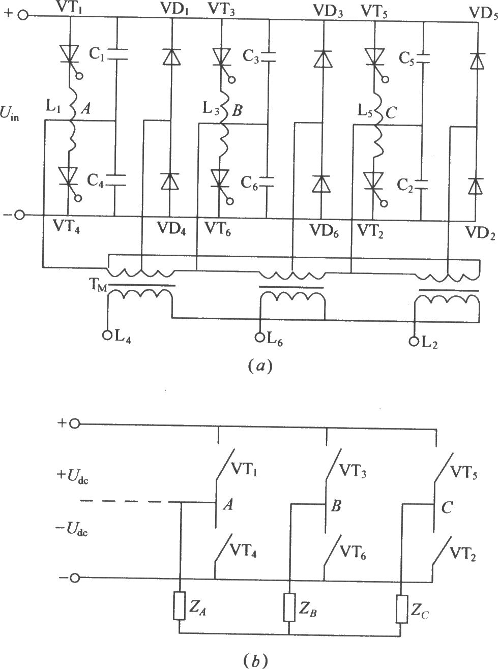
As shown in the figure is the traditional three-phase bridge type inverter circuit:VT1~VT6 is thyristor, L1~L6 is commutation reactor, C1~C6 is commutating capacitor, the thyristor shut-off circuitconsists of the two parts. VD1~VD6 is feedback diode. According to the work principle of the thyristor, it based on the 3-phaseAC inputpower supply , If the thyristor bearthe maximumpositive anode voltage and the control gate gets trigger pulse, it will switch to conducting state. On the contrary the thyristor under the conducting state with the enough inverse anode voltage will switch to cut off state. The figure(b) is the simplified figure of figure(a).
Reprinted Url Of This Article:
http://www.seekic.com/circuit_diagram/Basic_Circuit/Three_phase_bridge_type_inverter_circuit_diagram.html
Print this Page | Comments | Reading(3)

Article Categories
power supply circuit
Amplifier Circuit
Basic Circuit
LED and Light Circuit
Sensor Circuit
Signal Processing
Electrical Equipment Circuit
Control Circuit
Remote Control Circuit
A/D-D/A Converter Circuit
Audio Circuit
Measuring and Test Circuit
Communication Circuit
Computer-Related Circuit
555 Circuit
Automotive Circuit
Repairing Circuit
Code: