Communication Circuit
Phase locked loop secondary frequency conversion wireless transceiver circuit corresponds the industrial remote control GB
Published:2011/7/25 21:48:00 Author:Christina | Keyword: Phase, locked loop, secondary frequency, conversion, wireless, transceiver circuit, industrial, remote control, GB | From:SeekIC
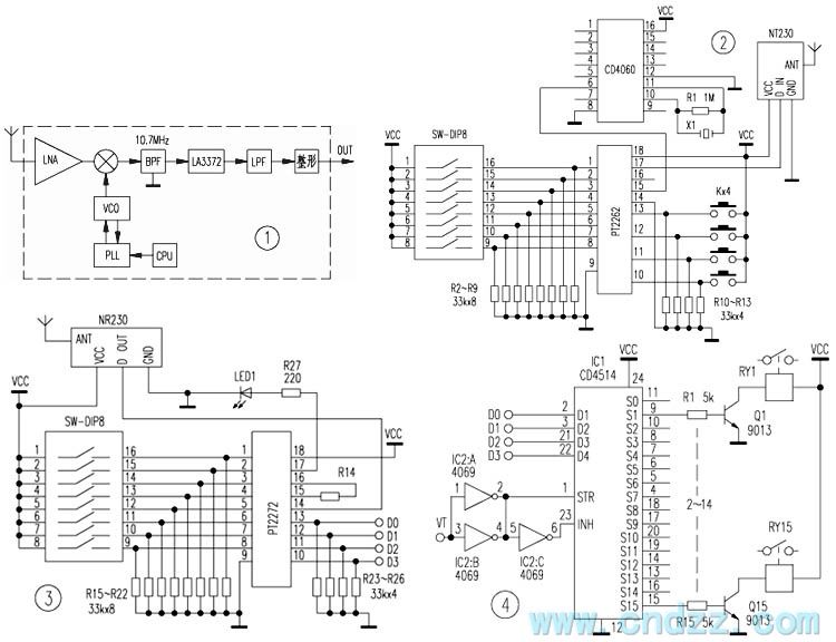
The NT230 launch module uses the special import high stability crystal (it is not the surface acoustic wave resonator). It outputs the stable 230MHz radio frequency FSK signal, and the emission current is very small, when the power is 5V/8mA, the output voltage is 110dBuV (75Ω load).
The NR230 receiving module diagram is as shown in figure 1, the modulated coded signal which is from the antenna is amplified and mixed by the circuit, then it is sent into the second mixer which is composed of the LA3372, after the original signal is detected out, it gets through the low-pass circuit and the amplification shaping circuit.
Reprinted Url Of This Article:
http://www.seekic.com/circuit_diagram/Communication_Circuit/Phase_locked_loop_secondary_frequency_conversion_wireless_transceiver_circuit_corresponds_the_industrial_remote_control_GB.html
Print this Page | Comments | Reading(3)

Article Categories
power supply circuit
Amplifier Circuit
Basic Circuit
LED and Light Circuit
Sensor Circuit
Signal Processing
Electrical Equipment Circuit
Control Circuit
Remote Control Circuit
A/D-D/A Converter Circuit
Audio Circuit
Measuring and Test Circuit
Communication Circuit
Computer-Related Circuit
555 Circuit
Automotive Circuit
Repairing Circuit
Code: