Position: Home > Circuit Diagram > Electrical Equipment Circuit > IC_precision_waveform_generator_with_variade_duty_cycle
Electrical Equipment Circuit
IC_precision_waveform_generator_with_variade_duty_cycle
Published:2009/7/25 4:21:00 Author:Jessie | From:SeekIC
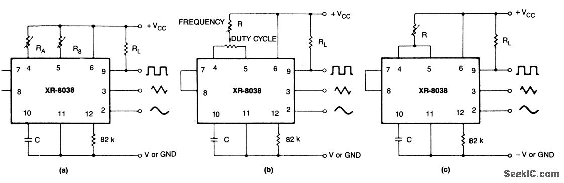
These circuits are similar to that of Fig 5-47,exceptfor alternate timing configurations and a duty-cycle control, If two separate timing resistors are used (Fig. 5-48A), the output frequency is: f= 0.3/RC, where RA= RB = R. If one timing resistor is used (Fig. 5-48B or 5-48C), the output frequency is: f =0.15/RC. If the duty cycle is to be varied over a small range, it should be centered around a duty cycle of 50%.
Reprinted Url Of This Article:
http://www.seekic.com/circuit_diagram/Electrical_Equipment_Circuit/IC_precision_waveform_generator_with_variade_duty_cycle.html
Print this Page | Comments | Reading(3)

Article Categories
power supply circuit
Amplifier Circuit
Basic Circuit
LED and Light Circuit
Sensor Circuit
Signal Processing
Electrical Equipment Circuit
Control Circuit
Remote Control Circuit
A/D-D/A Converter Circuit
Audio Circuit
Measuring and Test Circuit
Communication Circuit
Computer-Related Circuit
555 Circuit
Automotive Circuit
Repairing Circuit
Code: