Telephone-Related Circuit
Anti-toll-fraud sound and light annunciator circuit diagram
Published:2011/9/13 6:48:00 Author:Vicky | Keyword: anti-toll-fraud, sound and light annunciator circuit | From:SeekIC
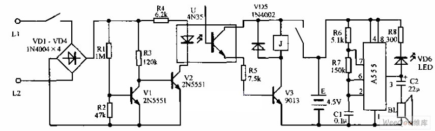
Anti-toll-fraud sound and light annunciator circuit diagram is shown in the above picture. The picture is an anti-toll-fraud sound and light warning circuit. It is assembled in the junction box of service entrance conductor. It normally does not consume power or affect the normal work of telephone. When anyone uses the line to make calls stealthily, the luminous diode shrinks, and the annunciator sound sends out warning. Because the voltage of the exterior line of the telephone is higher, the diode VD1~VD4 adopts 1N4004 type diode. Triode V1 and V2 use small-power high reverse voltage tube, such as types (PNP type, note that the polarity of the power supply should be changed) of 2N5551 (it’s reverse voltage is 160V) or 2N5401. The relay K adopts 4098 of small size, and the work voltage uses 3V.
Reprinted Url Of This Article:
http://www.seekic.com/circuit_diagram/Electrical_Equipment_Circuit/Telephone-Related_Circuit/Anti_toll_fraud_sound_and_light_annunciator_circuit_diagram.html
Print this Page | Comments | Reading(3)

Article Categories
power supply circuit
Amplifier Circuit
Basic Circuit
LED and Light Circuit
Sensor Circuit
Signal Processing
Electrical Equipment Circuit
Control Circuit
Remote Control Circuit
A/D-D/A Converter Circuit
Audio Circuit
Measuring and Test Circuit
Communication Circuit
Computer-Related Circuit
555 Circuit
Automotive Circuit
Repairing Circuit
Code: