power supply circuit
Controlled silicon switching stabilized voltage supply
Published:2011/11/14 2:30:00 Author:May | Keyword: Controlled silicon, switching stabilized voltage supply | From:SeekIC
When controlled silicon switching stabilized voltage supply is normal working, it uses very small control currentto control very high anode current.
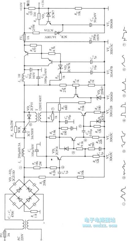
The diagram showsa practical circuit of controlled silicon ripples trigger type switching stabilized voltage supply. It shapes and enlarges of rectified ripple. Then it can trigger controlled silicon and make it break over. When the momentary value of rectified voltage is dropping to 0V, controlled silicon will becut off byitself. It can achieve voltage regulation by using the changes of output voltage to control the leading edge of trigger pulse.
Voltage regulator circuit mainly consists of transistors VT1~VT4, transformer T, controlled silicon SCR1, etc.
When the power supply turns on, rectifier can output pulse DC voltage like wave ①. It adds to the base of VT4 after diving by R2 and R3, the wave is shown in ②. VT4 can enlarge it, then collector output pulse can charge to C7 through R8, so it can generate run up saw-tooth wave. The wave is sent to the base of VT3 through R7, its wave is shown in ③.
Reprinted Url Of This Article:
http://www.seekic.com/circuit_diagram/Power_Supply_Circuit/Controlled_silicon_switching_stabilized_voltage_supply.html
Print this Page | Comments | Reading(3)

Article Categories
power supply circuit
Amplifier Circuit
Basic Circuit
LED and Light Circuit
Sensor Circuit
Signal Processing
Electrical Equipment Circuit
Control Circuit
Remote Control Circuit
A/D-D/A Converter Circuit
Audio Circuit
Measuring and Test Circuit
Communication Circuit
Computer-Related Circuit
555 Circuit
Automotive Circuit
Repairing Circuit
Code: