power supply circuit
Frequency modulation type switching stabilized voltage supply 1
Published:2011/11/22 0:27:00 Author:May | Keyword: Frequency modulation, switching, stabilized voltage supply | From:SeekIC
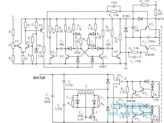
In the diagram, VT5 and VT6 make up the impulse oscillator. It has high response speed and wide frequency adjustable range. The reason is that the base driver and timing loopare separating, and they can work by themselves without disturbing. Frequency regulation is finished by comparator amplifier composed of VT1, VT2 and VT3.
Power switching tubesare VTT10, VT11 VMOS tubes. It can make influence onthe switching tube turning on speed and cutting off speedif input capacitor is too high. In order to overcome this problem, we can add a compensation circuit composed of R22 and CI0 on the primary of isolation transformer T2. After that, when the circuit is open, the primary of T2 has a higher voltage about 18V; when the tube is closed, the amplitude is already dropped down. It has about 11V voltage. When the circuit is open in the next time, the amplitude is already recovery again.
Reprinted Url Of This Article:
http://www.seekic.com/circuit_diagram/Power_Supply_Circuit/Frequency_modulation_type_switching_stabilized_voltage_supply_1.html
Print this Page | Comments | Reading(3)

Article Categories
power supply circuit
Amplifier Circuit
Basic Circuit
LED and Light Circuit
Sensor Circuit
Signal Processing
Electrical Equipment Circuit
Control Circuit
Remote Control Circuit
A/D-D/A Converter Circuit
Audio Circuit
Measuring and Test Circuit
Communication Circuit
Computer-Related Circuit
555 Circuit
Automotive Circuit
Repairing Circuit
Code: