Power-Supply Circuits-High Voltage
24V CRT high voltage power supply circuit diagram
Published:2011/4/14 2:42:00 Author:Ecco | Keyword: 24V, CRT, high voltage, power supply | From:SeekIC
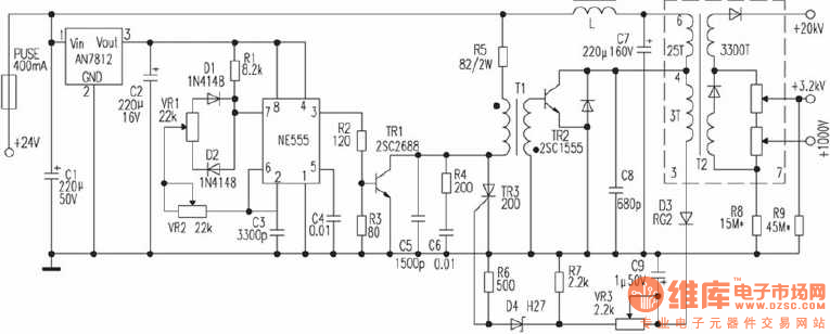
Some cameras use 11.4cm (4.5 inches) pure flat CRT as the display component, the anode voltage of high-voltage components is +20 kV, focus electrode voltage is +3.2 kV, accelerating voltage is +1000 V, the power supply of high voltage components is DC in 24V. It's as the chart shown:
Basic principles: NE555 constitutes pulse generator, to adjust potentiometer VR2 can generate a pulse with the frequency in about 20kHz, potentiometer VR1 adjusts the pulse width. TR1 is driver stage, the pulse transformer T1 adopts reverse polarity excitation, that is TR1 being on while TR2 being off, TR2 being on while TR1 being off, D3, C9, VR3, R7 and D4, R6, TR3 form a high-voltage protection circuit. VR2 is used for adjusting the frequency, and VR2 is used for adjusting the size of high voltage.
VR2 uses precision adjustable resistors. T2 can adopt colour TV line output transformer. The writer uses the Toyo SE-1438G Series of 35cm (14 inch) color TV line output transformer, with the anode voltage up to 20kV, and then choose the resistance of R8 to make acceleration voltage be +1000 V, the resistance of R9 make the focus electrode voltage be +3.2 kV. The whole part is packaged with aluminum box, aluminum jacket is connected to the earth to reduce the interference on the circuit.
Reprinted Url Of This Article:
http://www.seekic.com/circuit_diagram/Power_Supply_Circuit/Power-Supply_Circuits-High_Voltage/24V_CRT_high_voltage_power_supply_circuit_diagram.html
Print this Page | Comments | Reading(3)

Article Categories
power supply circuit
Amplifier Circuit
Basic Circuit
LED and Light Circuit
Sensor Circuit
Signal Processing
Electrical Equipment Circuit
Control Circuit
Remote Control Circuit
A/D-D/A Converter Circuit
Audio Circuit
Measuring and Test Circuit
Communication Circuit
Computer-Related Circuit
555 Circuit
Automotive Circuit
Repairing Circuit
Code: