Signal Processing
Comparing_voltages_of_opposite_polarity
Published:2009/7/24 4:40:00 Author:Jessie | From:SeekIC
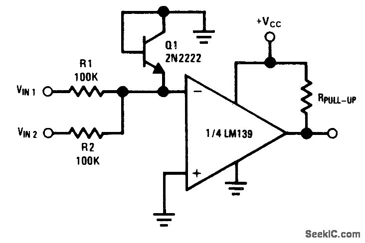
Fig. 15-22 This circuit compares the magnitude of VIN1 and VIN2, which have opposite polarities. The voltage at the inverting input of the LM139 is a function of VIN1, VIN2, R1, and R2. Diode-connected Q1 clamps the inverting terminal below ground for protection. If VIN1 is used for positive and VIN2 for negative, the output goes low (ground) if VIN1 is greater than VIN2. The output goes to near VCC if VIN1 is less than VIN2 National Semiconductor. Linear Applications Handbook, 1991, p. 260.
Reprinted Url Of This Article:
http://www.seekic.com/circuit_diagram/Signal_Processing/Comparing_voltages_of_opposite_polarity.html
Print this Page | Comments | Reading(3)

Article Categories
power supply circuit
Amplifier Circuit
Basic Circuit
LED and Light Circuit
Sensor Circuit
Signal Processing
Electrical Equipment Circuit
Control Circuit
Remote Control Circuit
A/D-D/A Converter Circuit
Audio Circuit
Measuring and Test Circuit
Communication Circuit
Computer-Related Circuit
555 Circuit
Automotive Circuit
Repairing Circuit
Code: