Basic Circuit
Voltage / frequency conversion circuit composed of NE555
Published:2011/7/10 22:23:00 Author:Lucas | Keyword: Voltage conversion , frequency conversion | From:SeekIC

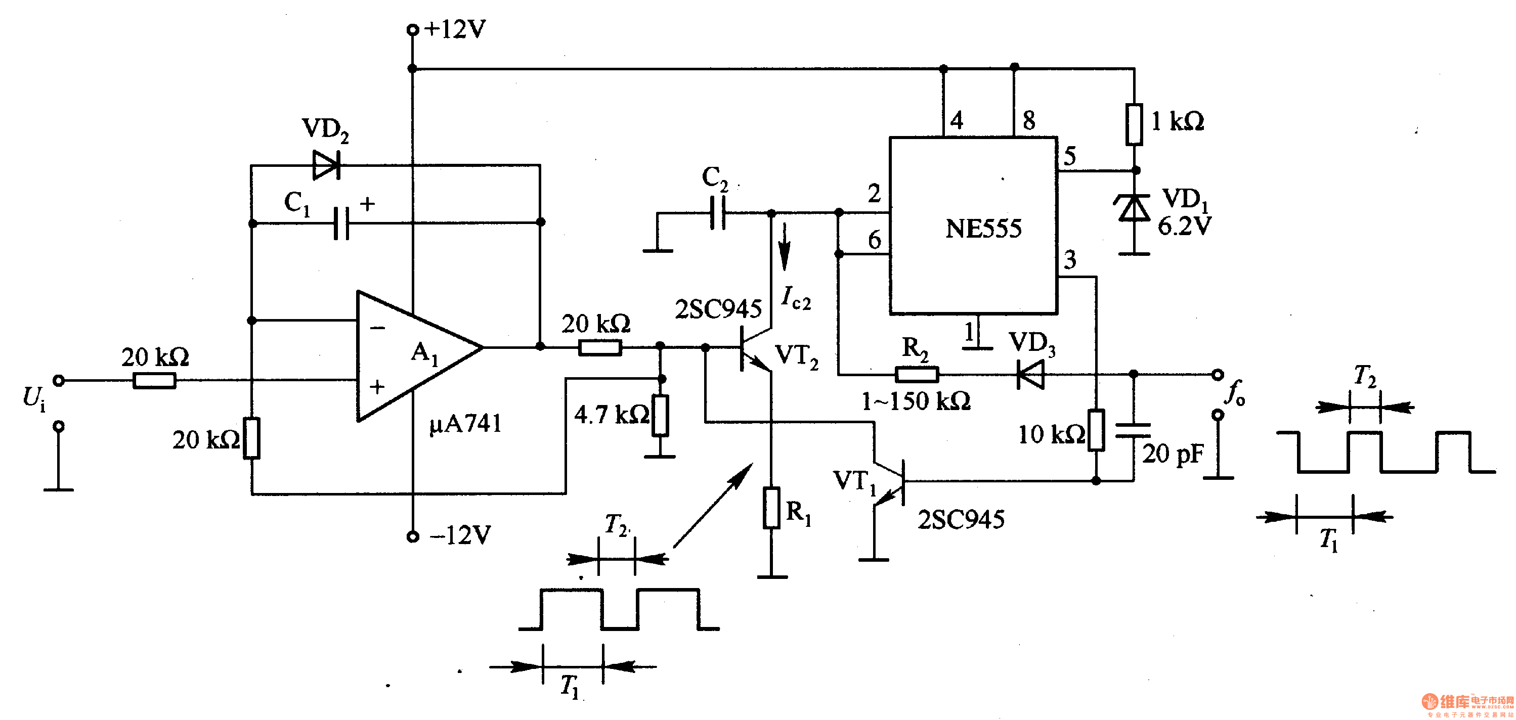
In the circuit, NE555's oscillation frequency is controlled by the VT2, and during its pin 3 in the low output waveform (output waveform of the T1 period), as VTI stops, VT2 is conduction with current Ic2 flowing, and the size is controlled by the output voltage of Al. C2 discharge time T1 = C2U2 / (2Ic2), in the formula, Uz is the stable voltage of VD1. NE555 output is in high level, the current flows VD3 by pin 3. R2 and C2 have current flowing. Then VTl is switched into saturated conduction, and the base of VT2 is equivalent to short-circuit, so VT2 ends, and the collector current Ic2 is zero.
Reprinted Url Of This Article:
http://www.seekic.com/circuit_diagram/basic_circuit/voltage___frequency_conversion_circuit_composed_of_ne555.html
Print this Page | Comments | Reading(3)

Article Categories
power supply circuit
Amplifier Circuit
Basic Circuit
LED and Light Circuit
Sensor Circuit
Signal Processing
Electrical Equipment Circuit
Control Circuit
Remote Control Circuit
A/D-D/A Converter Circuit
Audio Circuit
Measuring and Test Circuit
Communication Circuit
Computer-Related Circuit
555 Circuit
Automotive Circuit
Repairing Circuit
Code: