
Automatic Control
Index
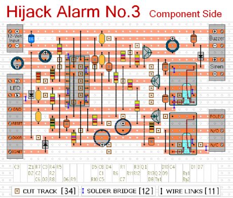
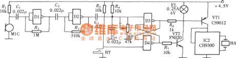
Hijack Alarm No.3 2
Published:2013/2/2 20:51:00 Author:muriel | Keyword: Hijack Alarm
View full Circuit Diagram | Comments | Reading(815)
Automatic level control with NE570
Published:2012/9/11 21:20:00 Author:Ecco | Keyword: Automatic level , control
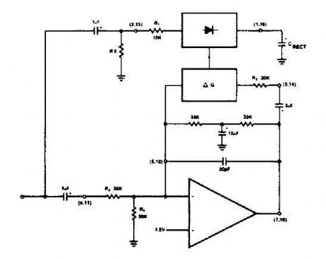
The NE570 can be used to make a high performance compressor FTA, except that the rectifier is connected to the input. This makes gain inversely proportional to the input level so that a drop of 20 dB input level will produce an increase of 20 dB gain. The output remains at a constant level. As shown, the circuit will maintain an output level of ± 1 dB for an input range of + 14 to -43 dB at 1 kHz. (View)
View full Circuit Diagram | Comments | Reading(0)
Car Wiper-Speed Controller
Published:2012/9/11 20:59:00 Author:Ecco | Keyword: Car, Wiper-Speed Controller
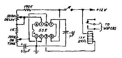
This 12V wiper speed controller circuit uses the 555 timer. And can be fitted to any car. Its one of those very easy and usefull circuits. (View)
View full Circuit Diagram | Comments | Reading(1)
LM139/239/339 Low power consumption low disorders voltage comparator circuit
Published:2011/9/13 20:29:00 Author:Fiona | Keyword: Low power consumption, low disorders, voltage comparator
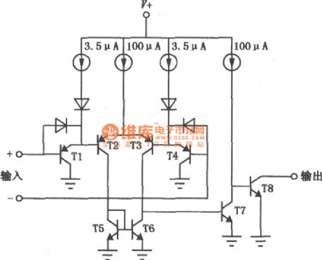
LM139/239/339are kind of excellent performance, wide application of the voltage comparator.Its consumption is small,offset current is low and bias current is small,it can be single power supply,the output end is compatible with a variety of logic circuit (TTL / DTL / ECL / MOS / CMOS),each package has four independent comparators.Its interior circuit and the same phase voltage comparator with lag function are shown above.
(View)
View full Circuit Diagram | Comments | Reading(1890)
Theory of Land Cruiser 70 Light Cross-country Car Engine Control and its Ignition
Published:2011/9/12 23:52:00 Author:Zoey | Keyword: Land Cruiser, 70 Light Cross-country Car, Engine Control, Ignition
Figure: Theory of Land Cruiser 70 Light Cross-country Car Engine Control, Ignition (22R-E,22R motor)
13 a fuel injector; 14 an electronic fuel injection systems (EFI) Main relay; 15 - fuel pump relay; 16 a fuel pump motor; 17 a knock sensor; 18 an oxygen sensor; 19 an air flow meter; 20 a fault detection socket; 21 - valve fuel pressure increases; 22 an air injection system valve; 23 an engine electronic control unit (ECU); 24 an engine warning light detection; 25 a coolant temperature sensor; 26 a throttle position sensor; 27 point fire coil; 28 point fire module (electronic components); 29 a distributor (22R-E engine); 30 A contact-type distributor (22R engine); 31,40 a - anti-interference filter; 92 a speed sensor; 113 a brake light switch; 69 a combination of dashboard 6C terminal (tachometer); 69-7D - four-wheel drive indicator light (View)
View full Circuit Diagram | Comments | Reading(859)
the agricultural liquid level automatic control circuit consisting of NE555
Published:2011/8/20 2:13:00 Author: | Keyword: the agricultural liquid level, automatic control
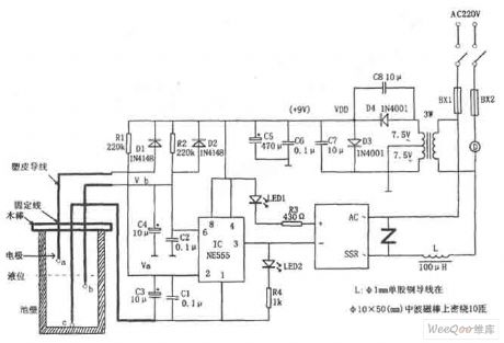
If just turns on the power ,the IC (555) ② pin is low level due to the voltage on C3 can't mutations when there isno water in the pool, 555 is set,high level outputby3-pinmakes the SSR end and the motor D is not running. At this point C3,C4 charge respectively through R1, R2, when the voltage on C4 charges to 2/3VDD, IC is reset,low level output by 3-pin makes SSR internal photoelectric coupler connect the AC voltage 220V, motor D has electricity and runs to pump water. When the water level rises to b probe, C4 is discharged through the water, but 555 still outputs low level,the motor D continues to run.
(View)
View full Circuit Diagram | Comments | Reading(3696)
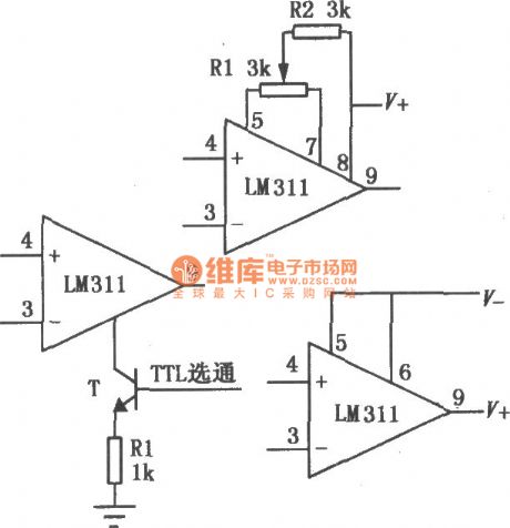
High-speed complementary output voltage comparator circuit
Published:2011/8/20 2:10:00 Author: | Keyword: High-speed, complementary output, voltage comparator
LM161/261/361 transmission speed is high,it has the general power supply voltage and independent strobe terminal, it can output two complementary TTL signal that delays small and theinput disorder voltage is small,when driving over,the switching speed is small and it uses dual in-line type.The high-speed peak detector is shown as above.
(View)
View full Circuit Diagram | Comments | Reading(884)
Timing Controller (the 2nd)
Published:2011/8/12 4:53:00 Author:Felicity | Keyword: Timing Controller
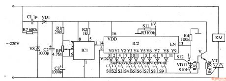
Work of the circuit
The circuit consists of Power supply circuit, pulse generator, control implementation delay circuit and control circuit. ( It is showed in picture 8-91.)
Power supply circuit consists of buck capacitor Cl, discharge resistor R7, voltage regulator diode VS, the rectifier diode VDl and filter capacitor C2.
Pulse generator consists of time-base integrated circuit ICl, resistors Rl and R2, potentiometers RP and capacitors C3.
Control implementation delay circuit consists of decimal counting / pulse distributor circuit IC2, resistors R3 and R4, diode VD2-VD11, switch S1-S12.
Control circuit consists of transistor V, resistors R5 and R6, thyristor VT and AC contactor KM. (View)
View full Circuit Diagram | Comments | Reading(1022)
Low-end Car Charger Circuit Diagram Achieved by Single Chip 34063
Published:2011/9/3 10:13:00 Author:Zoey | Keyword: Low-end, Car Charger, Single Chip 34063
Advantage: Low cost
Disadvantage:
(1) Undesirable reliability, single performance, no overtemperature and short circuit-proof measures.
(2) Inputs direct current voltage, but controls input constant charge current by limiting maximum switched current peak, its precision is not accurate enough.
(3) As 34063 belongs to a 1.5-A switched current PWM+PFM mode (no interior error magnifier), its automobile charge inputs relatively larger wave of direct voltage and current, the wave is not pure enough and its ability to input current is limited. (often been seen in low-end automobile charge ranging from 300 ma to 600 ma) (View)
View full Circuit Diagram | Comments | Reading(863)
Control and driving circuit diagram of three-phase DC motor in Y connection
Published:2011/9/6 22:52:00 Author:Vicky | Keyword: control and driving circuit, three-phase DC motor, Y connection
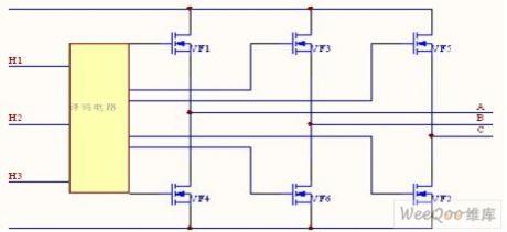
In this circuit, the three-phase winding of the motoris in Y connection. If one is conducted by another, when power diode VF1 and VF2 are conducted, the current flows to A phase winding, and then back to the power supply by C phase winging after flowing through VF2. If the torque generated by the current which flows to the windings is positive, then the torque generated by windings is negative. When the motors turnfor60 degrees, VF2 andVF3 are conducted instead of VF1 and VF2. Meanwhile, the current flows to B phase winding from VF3, and then back to the power supply by C phase winding after flowing through VF2. (View)
View full Circuit Diagram | Comments | Reading(1347)
Eight groups electronic responser circuit with CD4043,LM386
Published:2011/8/25 20:16:00 Author:chopper | Keyword: Eight groups, electronic responser
The eight groups electronic responser circuit can be used by 8 participants,and it is of functions like interlock and sound and light indication,which is shown as picture. Circuit consists of button input of eight groups and interlock circuit, sound and light indication circuit, reset circuit and the power supply circuit. (View)
View full Circuit Diagram | Comments | Reading(1866)
SST8803,UM3758-108A data transmission modulation and demodulator circuit
Published:2011/8/25 20:21:00 Author:chopper | Keyword: data transmission, modulation, demodulator
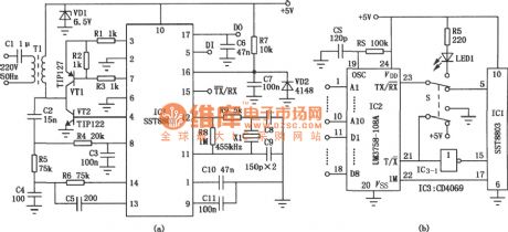
The main components IC1 of the circuit is the modulation/demodulation IC SST8803 of new grid carrier digital pulse signal transmission,it has low power consumption, high sensitivity, good anti-jamming and good anti-static performance,and the single chip can complete all the work including the data signal modulation,send and receive, demodulation. It can use low-voltage power lines, broadcast cable and closed television signal lines as carriers for data exchange of information, can also be used for some systems like remote telemetry, centralized alarm,multi-channel paging and microcomputer network.
(View)
View full Circuit Diagram | Comments | Reading(2343)
CW117,CW217,CW317 Ac peak clip circuit
Published:2011/8/25 20:22:00 Author:chopper | Keyword: Ac peak, clip circuit
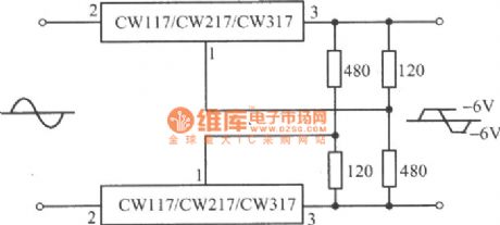
View full Circuit Diagram | Comments | Reading(944)
LM111,211,311 single voltage comparator
Published:2011/8/25 20:22:00 Author:chopper | Keyword: single voltage, comparator
The power supply voltage range of LM111/211/311 is big(± 5V~± l5V), bias current is small, offset current is small, and differential input voltage range is big(± 30V),and its output is compatible with TTL, DTL and MOS circuit , and it can drive the indicator light and relay. It adopts either single power supply or dual power supply, and has two forms of collector output and emitter output . This comparator also has the external balance adjustment end and the gate control side, and it can be selected or adjusted when it is in usage. The basic circuit is shown as picture.
(View)
View full Circuit Diagram | Comments | Reading(1172)
Electronic decorative peacock flaunting circuit of CD4017,NE555
Published:2011/7/26 6:06:00 Author:chopper | Keyword: Electronic, decorative, peacock flaunting
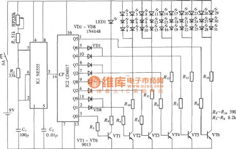
Electronic decorative peacock flaunting includes 10-group light-emitting diodes,each LED contains multiple light-emitting diodes, and these LEDs are installed on the tail of the peacock in.And under the drive of the light-driven circuit,these LEDs shine circularly and radially by the fan shape,which is like the peacock flaunting,and itis shown as picture. It consists of LED drive circuit, drive pulse oscillator and LEDs. (View)
View full Circuit Diagram | Comments | Reading(3838)
electronic all birds paying homage to the phoenix NE555,CD4017 circuit
Published:2011/8/25 20:14:00 Author:chopper | Keyword: electronic, all birds paying homage to the phoenix
View full Circuit Diagram | Comments | Reading(1310)
Electronic birthday candle circuit
Published:2011/7/26 5:35:00 Author:chopper | Keyword: Electronic, birthday candle
Electronic birthday candle includes a candle and a Happy Birthday Song. It imitates the shape of traditional birthday candles and adopts the operation mode like lighting and blowing candle, it is very interesting, the circuit is shown as picture. It consists of a 412 input end and nand-gate CD4011,and D3, D4 form the trigger RS, it uses two output states of trigger to control the lighting, blowing as well as the play and stop of the candle.
(View)
View full Circuit Diagram | Comments | Reading(1829)
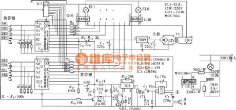
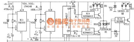
touch type voltage regulator circuit of NE555,CD4017
Published:2011/7/25 2:45:00 Author:chopper | Keyword: touch type, voltage regulator
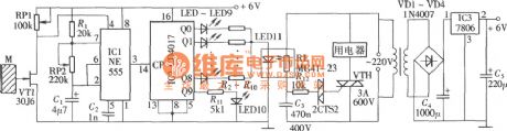
The picture shows the touch type voltage regulator,which can adjust the photoconductive resistance mainly by changing the brightness of LED,and then adjust the conduction degree of the bidirectional thyristor through triggering the diode trigger circuit, and ultimately achieve the purpose of the voltage regulation.The circuit is shown as picture.It consists of bidirectional thyristor trigger circuit, LED brightness adjustment circuit as well as regulating impulse generation and control circuit.
(View)
View full Circuit Diagram | Comments | Reading(1554)
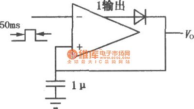
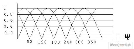
LM555 broad dynamic pulse width modulator circuit
Published:2011/7/24 3:36:00 Author:chopper | Keyword: broad dynamic, pulse width, modulator
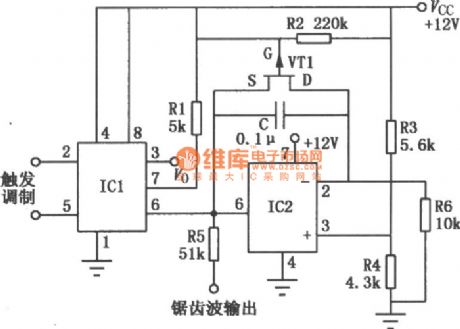
Broad dynamic pulse width modulator is mainly formed by the integrated timer circuit and integral circuit. As a result of op-amp, the temperature stability is good, linear dynamic range is wide, and the narrowest output pulse is 2μs, the widest pulse is 6ms,the ratio of wide, narrow pulse can reach 300:1. With the change of the modulativon input signal, the corresponding change of output pulse width will happen, resulting in the effect of pulse-width, and it can also output a saw-tooth-wave voltage signal at the same time.
(View)
View full Circuit Diagram | Comments | Reading(1678)
CD4520 digital coded lock circuit
Published:2011/7/25 2:49:00 Author:chopper | Keyword: digital, coded lock
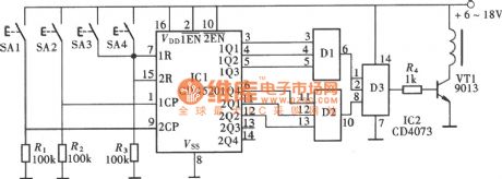
Figure shows the general-purpose digital coded lock circuit formed by the CMOS digital integrated circuit, which is characterized by a wide supply voltage range, low power consumption, anti-jamming performance, fewer external components.There are 256 password combinations, and it is of pseudo-code switch, and has a good security feature, the circuit is shown as figure.The coded lock circuit consists of a dual-binary synchronous add counter CD4520,and there are two binary counters of same structure in the circuit.
(View)
View full Circuit Diagram | Comments | Reading(2135)
| Pages:1/5 12345 |
Circuit Categories
power supply circuit
Amplifier Circuit
Basic Circuit
LED and Light Circuit
Sensor Circuit
Signal Processing
Electrical Equipment Circuit
Control Circuit
Remote Control Circuit
A/D-D/A Converter Circuit
Audio Circuit
Measuring and Test Circuit
Communication Circuit
Computer-Related Circuit
555 Circuit
Automotive Circuit
Repairing Circuit