
Automatic Control
Index 2
digital coded lock circuit with CD4520
Published:2011/7/22 3:29:00 Author:chopper | Keyword: digital, coded lock
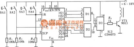
Figure shows the general-purpose digital coded lock circuit formed by the CMOS digital integrated circuit, which is characterized by a wide supply voltage range, low power consumption, anti-jamming performance, fewer external components.There are 256 password combinations, and it is of pseudo-code switch, and has a good security feature, the circuit is shown as figure.The coded lock circuit consists of a dual-binary synchronous add counter CD4520,and there are twobinary counters of same structure in the circuit.
(View)
View full Circuit Diagram | Comments | Reading(3129)
ultrasonic insect repellent circuit with CD4017
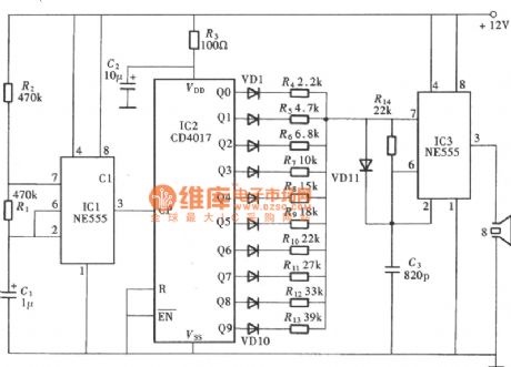
Published:2011/7/20 23:06:00 Author:chopper | Keyword: ultrasonic, insect repellent
View full Circuit Diagram | Comments | Reading(5434)
responder (CD4011) circuit with nand gate
Published:2011/7/20 23:43:00 Author:chopper | Keyword: responder circuit, nand gate

Quiz responder is a very typical interlock circuit.As long as one of participates first presses the responder,the others are invalid.The responder shown in the picture can be used for many people to attended the answer,in the circuit there are only two groups.And it can add some groups according to the actual need in the practical usage.And the circuit is shown as picture.Each group of the responders is formed by a answer button, an input control gate, a RS trigger and a luminescent indicator circuit.
(View)
View full Circuit Diagram | Comments | Reading(1643)
AUTO_FADE
Published:2009/7/2 4:30:00 Author:May
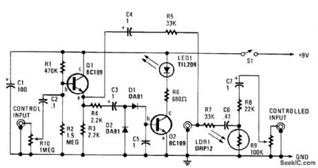
The automatic fader drops the level of the background music when the narration comes up. The control input goes through R10, a preset audio level control, to the input of an emitter-follower buffer stage (Q1). The buffer offers a high input impedance and makes sure that the source impedance is low enough to drive the rectifier and smoothing circuit, which consist of D1, D2, and C5. The smoothed output drives a simple LED circuit. R8 and LDR1 form an input attenuator across which the output is fed via C6 and C7 to the output jack. The output at the emitter of Q1 couples to this socket through C4 and R5. R5 and R7 are a passive mixer. With 200 mV or less at the input, there isn't sufficient voltage across C5 to make Q2 turn on. Over 200 mV, Q2 does turn on to a limit, and the LED gets power. That makes the LDR's resistance fall, and signal loss through the attenuator increases. Increase the input to 350 mV rms, and you get a signal reduction of better than 20 dB. (View)
View full Circuit Diagram | Comments | Reading(1187)
Addition and subtraction counter within 100 circuit
Published:2011/7/28 4:14:00 Author:John | Keyword: Addition and subtraction counter

Addition and subtraction counter within 100 circuit is shown.
(View)
View full Circuit Diagram | Comments | Reading(955)
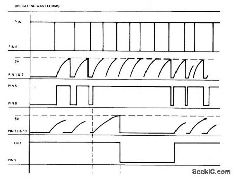
OPERATING_WAVEFORMS
Published:2009/6/24 4:03:00 Author:May
View full Circuit Diagram | Comments | Reading(0)
Fan speed controller diagram 1
Published:2011/6/27 20:25:00 Author:Nora | Keyword: Fan , speed , controller
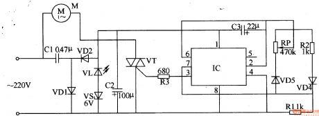
Step-down power supply circuit consists of the capacitor Cl, rectifier diodes VDl, VD2, filter capacitor C2, the power indicator light-emitting diode composed of VL and VS regulator diode.Controlled oscillator consists of a time-base integrated circuit IC, resistors RI, R2, capacitors C3, potentiometer RP and diode VD3, VD4 formed.Control implementation of the circuit consists of the fan motor M, thyristor VT, resistor R3 and the first 3 feet inside the IC circuit.AC 220V voltage buck by Cl, VDl and VD2 rectified, VL and VS filtered and C2 regulated, the IC provides about 8V DC voltage.Controlled oscillator work, a 3-pin output from the IC cycle 105, the duty cycle adjustable oscillating pulse signal, the use of this pulse signal to control the conduction status of thyristor VT.Adjust the resistance of RP, you can change the pulse duty cycle (adjustment range of 1% -99%), control the level of the fan motor M speed, resulting in simulated natural wind (gusts period of 10s).Change the capacitance of C3, can change the oscillator weeks moon, thus changing the simulation of natural wind cycle. (View)
View full Circuit Diagram | Comments | Reading(2646)
Infrared remote control dimmer, speed controller diagram 1
Published:2011/6/26 20:36:00 Author:Nora | Keyword: Infrared, dimmer, controller
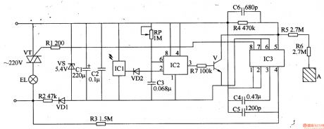
AC 220V voltage filtered by R2-limiting step, VDl rectifier, VS regulator and Cl, C2. It provide DC voltage about 5V for ICl-IC3 (Vcc).In pressing the remote control button, the remote control infrared remote control pulse(the time is less than 0.45 when press the remote control button , the remote control application output pulses 1-3; if the remote control button press time over .45 , the output of the remote control more than 3 Burst). 1C1 will receive the infrared pulse train amplification, demodulation, and plastic surgery and other treatment, output a low pulse, the VD2 turn, C3 quickly discharges. When the voltage across C3 is lower than Vcc / 3 时, IC2's output of 3 feet high, so that V conduction. When through a pulse train, VD2 end, +5 V voltage charging of C3 by the RP, the IC2 pin 2, 6-pin voltage rise, when the voltage is increased to 2Vcc / 3 时, lC2 flip-circuit, 3-pin change low, V cut-off. If the new moon in the C3 charge between ICl and output a low pulse, C3 will discharge again, then keep the output of IC2 3 feet high. (View)
View full Circuit Diagram | Comments | Reading(2599)
AUTOMATIC_PORCH_LIGHT_CONTROL
Published:2009/6/17 2:01:00 Author:May
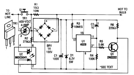
The automatic porch-light control circuit holds a triac on until a 4020 divider counts a number of 60-Hz powerline pulses. The circuit turns off a light after a predetermined time by using pins other than pin 3 of UI. Various times can be set. Consult the 4020 data sheet for information. (View)
View full Circuit Diagram | Comments | Reading(3533)
AUTO_TURN_SIGNAL_REMINDER
Published:2009/6/16 2:35:00 Author:May
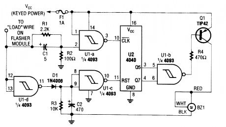
This circuit counts turn signal flashes. At the end of about 70 flashes, a chime sounds to remind the driver to turn off the turn signal. By using various taps on U2, the period can be changed if de-sired. BZ1 is a buzzer or chime module. (View)
View full Circuit Diagram | Comments | Reading(964)
NUCLEAR_REACTOR_STARTUP_CONTROL
Published:2009/7/13 1:05:00 Author:jailer


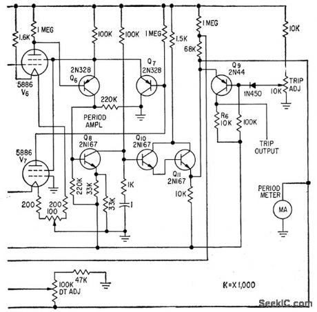


Logarithmic and period amplifers provide required wide indicating range without switching. Use of log diode V1 in series bock to back with V2 provides nonlinear element in which effects of changes in cathode temper ature and supply voltage are balanced out.V1 drives log amplifier consisting of balanced electrometer tubes V3 and V4, differential stage Q1-Q2, and cascaded emitter-followers Q3 and Q4. Period ampliler is a feedback-type differentiating circuit.-E. J. Wade and D.S. Davidson, Transistor Amplifers for Reactor Controls, Electronics, 32:21,p52-53. (View)
View full Circuit Diagram | Comments | Reading(931)
The automobile burglarproof alarm (1)
Published:2011/7/23 3:19:00 Author:qqtang | Keyword: burglarproof alarm
The working principle of the circuit The trigger alarm emitter circuit consists of the electric switch circuit, regulated filter circuit and encoding wireless emitter circuit, see as figure 7-78.
The electric switch circuit consists of the burglar switch S2, thyristor VT, transistors of V1 and V2, diodes of VD1 and VD2, resistors R1-R3, capacitors of C1 and C2, regulated diode VS1 and so on. The regulated filter circuit consists of the 3-terminal regulator IC1 and filter capacitor C3 (View)
View full Circuit Diagram | Comments | Reading(656)
Light control road lamp automatic control circuit
Published:2011/7/14 23:14:00 Author:Fiona | Keyword: Light control road lamp, automatic control
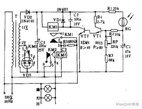
Connected to 220v AC power,the both ends of capacitor C4 will obtain ten 12v DC.At night,photoresistance RG is a high resistance,transistor VTl, v1,v2 are closed.The relay KMl has no power,the contacts 2-3 of KMl are closed.AC relay KM2 works with power.The contacts l-2 ,4-5 of KM2 are closed, light-emitting diode vD3 displays $signal instructions,floodlight H automatically kindle.At dawn,RG is a low resistance,VT1 conducts when it obtains base current,the radiation high potential output makes vT2 saturated conductivity. (View)
View full Circuit Diagram | Comments | Reading(948)
VFC100 synchronizing voltage / frequency converter circuit
Published:2011/7/26 6:28:00 Author:Fiona | Keyword: synchronizing voltage / frequency, converter
VFC100 is asynchronizing voltage / frequency converter which has strong function and it uses charge balance technology.Strict reset combined cycle is from the external clock frequency,it can better eliminate errors and the external timing components' drifting required by other converters. It also uses high-precision input resistor to set full scale input voltage,in many applications,it can obtain the required accuracy without external adjustment.Its typical application circuit is shown as above.
(View)
View full Circuit Diagram | Comments | Reading(792)
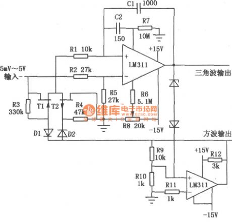
The typical application circuit of LM111/211/311
Published:2011/7/20 20:08:00 Author:Fiona | Keyword: typical application

View full Circuit Diagram | Comments | Reading(937)
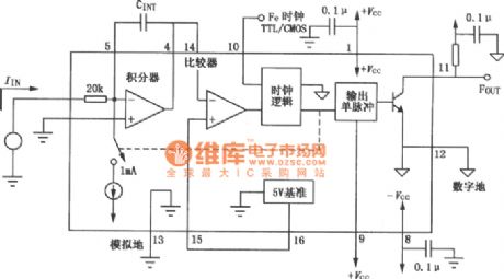
VFC62 voltage / frequency,frequency / voltage converter circuit
Published:2011/7/21 3:37:00 Author:Fiona | Keyword: voltage / frequency, frequency / voltage, converter

VFC62 voltage / frequency,frequency / voltage converter can easily convert analog signals into digital signals.The digital output uses the form of open collector,digital pulse repetition rate is proportional to the amplitude of the input analog voltage,the output pulse level is compatible with DTL,TTL and CMOS logic family.As shown in figure is its typical application circuit.
(View)
View full Circuit Diagram | Comments | Reading(4652)
Infrared sensing automatic door control circuit diagram with KC778B
Published:2011/5/17 3:16:00 Author:Ecco | Keyword: Infrared sensing , automatic door , control circuit
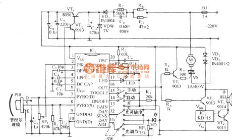
The circuit is shown as the chart. It is a control circuit which composed of infrared specific integrated circuit KC778B and KC778B is the center of the circuit. It’s surrounded by a pyroelectric infrared sensor head PIR, light control and light control adjustment circuit, a three-state select control, automatic restart function and manual control block status sensing functions and so on. (View)
View full Circuit Diagram | Comments | Reading(4170)
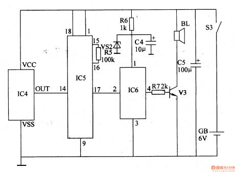
Infrared sensing automatic startup control circuit diagram with SR5553
Published:2011/5/13 4:29:00 Author:Ecco | Keyword: Infrared sensing automatic startup control
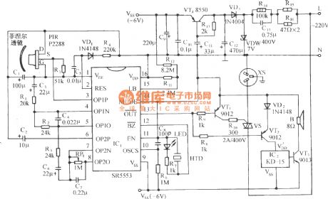
The circuitry shows as below: It includes pyroelectric infrared sensor head, infrared sensor control circuit, SCR control circuit, music sound circuit and exchange step-down rectifier circuit, etc. This control circuit can be used as control of automatic fan boot, automatic, energy-saving lamps, security, automatic interpretation etc. Pyroelectric infrared sensor head includes pyroelectric infrared sensor P2288 and the Fresnel optical lenses. The latter connects the infrared radiation that is from human body energy, to improve the detection range. The Fresnel lens have all sorts of different specifications, common have Q - 6 type, Q1A type and Q - 8 type, etc. To make energy‘s largest gathered, it requests lens face and infrared sensors to keep a certain distance, to different lens, their spotlighting distance is different. The reasonable configuration and installing can make detection distance be improved greatly. P2288 will detect the infrared radiation that from the pedestrians, then make impedance matching and magnifiing by the filter, signal mosfet (FET), emitted by source S to the signal input (IC1 OP1P) pin 3. (View)
View full Circuit Diagram | Comments | Reading(1662)
Over-Voltage Protection Circuit Composed Of MC3X164 Series
Published:2011/7/13 8:01:00 Author:Robert | Keyword: Over-Voltage, Protection
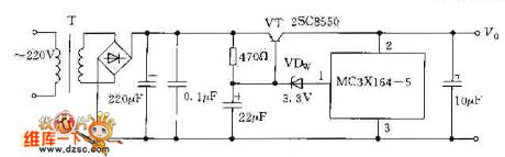
The picture shows the over-voltage protection circuit composed of MC3X164 series. (View)
View full Circuit Diagram | Comments | Reading(653)
water level automatic control circuit consisting of 555
Published:2011/7/8 2:28:00 Author:Fiona | Keyword: water level automatic control
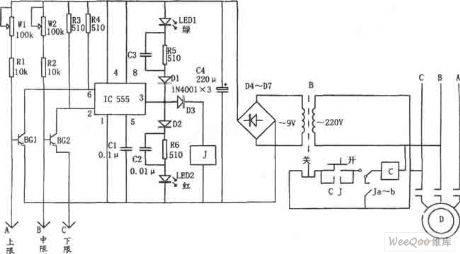
As shown in figure is water level automatic control circuit. The control circuit is composed of step-down rectifier circuit,water level measurement and control switch,flip and flop generator and so on.Step-down rectifier circuit provides VDD = 12 V power supply voltage for 555.Two steady state work patterns of 555 is used as RS trigger. BG1 and upper limit water level probe A are reset trigger switch; BG2 and the median probe B are setting trigger switch; C is the lower limit probe connecting to the ground electrical level. Using the characteristics of RS trigger and controlling the setting and resetting of 555 make the relay J absorb or release , so as to control the operation of the pumping motor D to make water level keep in the given upper limit and lower limit.
(View)
View full Circuit Diagram | Comments | Reading(1879)
| Pages:2/5 12345 |
Circuit Categories
power supply circuit
Amplifier Circuit
Basic Circuit
LED and Light Circuit
Sensor Circuit
Signal Processing
Electrical Equipment Circuit
Control Circuit
Remote Control Circuit
A/D-D/A Converter Circuit
Audio Circuit
Measuring and Test Circuit
Communication Circuit
Computer-Related Circuit
555 Circuit
Automotive Circuit
Repairing Circuit