
Automatic Control
Index 5
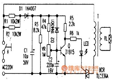
TLC336A bi-directional controllable thyristor application circuit
Published:2011/4/20 3:20:00 Author:Jessie | Keyword: bi-directional, thyristor, controllable, application
View full Circuit Diagram | Comments | Reading(1836)
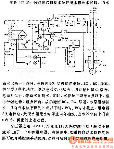
Automatic water level control circuit diagram of draining tank
Published:2011/4/7 21:20:00 Author:Ecco | Keyword: Automatic , water level control, draining tank
View full Circuit Diagram | Comments | Reading(1509)
Variable speed pick machine circuit diagram
Published:2011/4/1 1:03:00 Author:Rebekka | Keyword: Variable speed pick machine
Variable speed pick machine circuit diagram is shown as below.
(View)
View full Circuit Diagram | Comments | Reading(724)
Uncontrollable dual voltage circuit diagram
Published:2011/4/1 1:01:00 Author:Rebekka | Keyword: Uncontrollable dual voltage
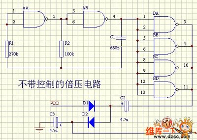
Uncontrollable dual voltage circuit diagram is shown as below.
(View)
View full Circuit Diagram | Comments | Reading(556)
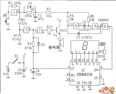
Anti-interference reset circuit diagram
Published:2011/4/1 0:59:00 Author:Rebekka | Keyword: Anti-interference reset
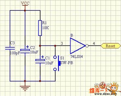
Anti-interference reset circuit diagram is shown as below.
(View)
View full Circuit Diagram | Comments | Reading(662)
Infrared micro-computer automatical pump fluid hardware design circuit
Published:2011/3/23 2:42:00 Author:Joan | Keyword: micro-computer , automatical pump fluid , Infrared pump fluid

The design uses a Microchip PIC16C54 microcontroller, selects GR40101 GD1611 infrared emitting diodes and silicon PIN photodiode as the infrared transmit and receive devices, chooses micro motors QDB-30-3.0 LCD driver as the pump. The system uses one-touch mode to complete suspension, setting the pump fluid volume and other functions.The circuit design uses power-saving mode with standby current less than 100μA, provides the necessary 500mA load current for micro-motor, and can monitor battery voltage, alarm when the battery is under voltage. System schematic is shown below.
In above figure, TX (infrared emission diode), R1, R5, Q4 constitute infrared emission circuit. Microcontroller port RA1 outputs certain frequency pulse to control transistor Q4 on or off, so as to control the transmit frequency of the infrared emission diode TX. MCU RA3 port provides power for the transmitter circuit for energy conservation. When RA1 port launchs pulse, RA3 port set high, firing circuit is power on. RX (infrared receiver), R2, R11, R12, R13, R16, Q6, C3 constitute infrared receiver circuit. RX receives infrared pulse, which is amplified by Q6 after being shaped.
Receiving circuit magnification must be strictly controlled to ensure the infrared reflection receive distance of about 10cm. Receiving circuit power is provided by the MCU port RB1. After the pulse launch, RB1 port sets high. R6, R7, R8, Q3 constitute battery voltage monitoring circuit. When the supply voltage drops to a certain value, Q3 cuts off, MCU port RB3 sets high, the circuit alarms for under-voltage. D2, D3, R9, R10, Q1, Q5 constitute the motor power supply circuit to provide the necessary 3V voltage and 500mA load current for the micro-motor. When needs to drive motor pump fluid, the microcontroller port RB2 output low voltage, Q emitter provides power supply for the motor. D1, C4, Q2, R3 constitute motor control circuit, it provides power supply for the motor first when pumps fluid, and then microcontroller port RA2 output high voltage to drive motor running. The LED is the work status indicator. The single function SW key, can set the pump fluid volume, pump fluid suspension, manual pump fluid and other functions. (View)
View full Circuit Diagram | Comments | Reading(1150)
| Pages:5/5 12345 |
Circuit Categories
power supply circuit
Amplifier Circuit
Basic Circuit
LED and Light Circuit
Sensor Circuit
Signal Processing
Electrical Equipment Circuit
Control Circuit
Remote Control Circuit
A/D-D/A Converter Circuit
Audio Circuit
Measuring and Test Circuit
Communication Circuit
Computer-Related Circuit
555 Circuit
Automotive Circuit
Repairing Circuit