
Other Circuit
Index 12
Composed of LM2641 5V/3A, 3.3V/4A, 12V/0.3A and 5V/0.025A four outputs power supply circui diagram
Published:2011/4/1 3:18:00 Author:Rebekka | Keyword: four output , power supply
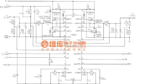
Composed of LM2641 5V/3A, 3.3V/4A, 12V/0.3A and 5V/0.025A four outputs power supply circui diagram. LM2641 is a dual adjustable step-down switch power supply controller. Output voltage 5.5~30V, 2.2~8V, dual output adjustable, working rate 300kHz, load regulation error 0.5%. Soft start available, with undervoltage and overvoltage protection.
(View)
View full Circuit Diagram | Comments | Reading(1069)
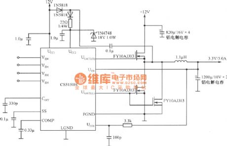
Composed of 4 codes synchronous step-down controller CS5150H 12V bias voltage 3.3V to 2.5V/7.0A converter circuit diagram
Published:2011/4/1 3:10:00 Author:Rebekka | Keyword: step-down controller , Composed of CS5150H, 3.3V to 2.5V/7.0A converter
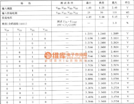
Composed of 4 codes synchronous step-down controller CS5150H 12V bias voltage 3.3V to 2.5V/7.0A converter circuit diagram is shown as below.
4-bit DAC codes feature:
(View)
View full Circuit Diagram | Comments | Reading(553)
Composed of 4 codes synchronous step-down controller CS5150H 5.0V to 3.3V/10A converter circuit diagram
Published:2011/4/1 3:07:00 Author:Rebekka | Keyword: step-down controller , 5.0V to 3.3V/10A converter
Composed of 4 codes synchronous step-down controller CS5150H 5.0V to 3.3V/10A converter circuit diagram is shown as below.
(View)
View full Circuit Diagram | Comments | Reading(561)
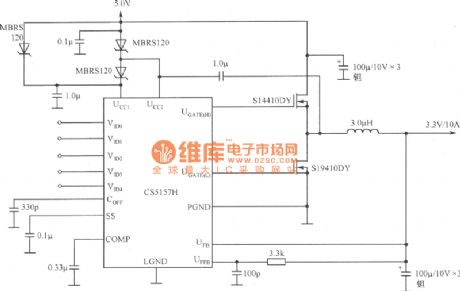
4 Codes Synchronous step-down controller composed of CS5150H current sharing 5.0V to 3.3V/10A converter circuit diagram
Published:2011/3/31 4:39:00 Author:Rebekka | Keyword: 4 Codes Synchronous, step-down controller current sharing
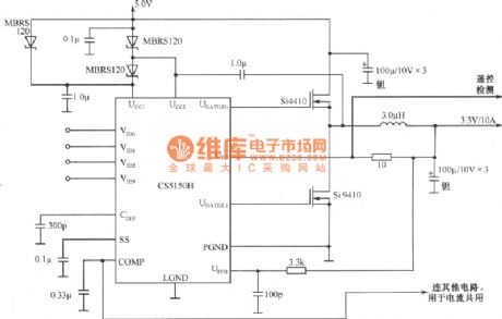
4 Codes Synchronous step-down controller composed of CS5150H current sharing 5.0V to 3.3V/10A converter circuit diagram is shown as below.
(View)
View full Circuit Diagram | Comments | Reading(535)
4 Codes synchronous step-down controller composed of CS5150H 5.0V to 3.3V/10A converter circuit diagram
Published:2011/3/31 4:44:00 Author:Rebekka | Keyword: Synchronous step-down controller, synchronous step-down controller

4 Codes Synchronous step-down controller composed ofCS5150H 5.0V to 3.3V/10A converter circuit diagram is shown as below.
(View)
View full Circuit Diagram | Comments | Reading(448)
Composed of CS5157H current sharing 5.0V to 3.3V/10A converter circuit diagram
Published:2011/3/31 4:44:00 Author:Rebekka | Keyword: current sharing , 5.0V to 3.3V/10A converter
Composed of CS5157H current sharing 5.0V to 3.3V/10A converter circuit diagram is shown as below.
(View)
View full Circuit Diagram | Comments | Reading(528)
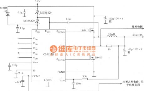
Composed of CS5157H l2V to 3.3V/5.0A remote testing converter circuit diagram
Published:2011/4/1 3:03:00 Author:Rebekka | Keyword: l2V to 3.3V/5.0A converter, remote testing
Composed of CS5157H l2V to 3.3V/5.0A remote testing converter circuit diagram is shown as below.
(View)
View full Circuit Diagram | Comments | Reading(474)
Composed of CS5157H 12V bias voltage 3.3V to 2.5V/7A converter circuit diagram
Published:2011/4/1 3:01:00 Author:Rebekka | Keyword: 12V bias voltage , 3.3V to 2.5V/7A converter
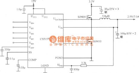
Composed of CS5157H 12V bias voltage 3.3V to 2.5V/7A converter circuit diagram is shown as below.
(View)
View full Circuit Diagram | Comments | Reading(875)
Composed of CS5157H 5.OV to 3.3V/10A converter circuit diagram
Published:2011/4/1 3:00:00 Author:Rebekka | Keyword: 5.OV to 3.3V/10A converter
Composed of CS5157H 5.OV to 3.3V/10A converter circuit diagram is shown as below.
(View)
View full Circuit Diagram | Comments | Reading(522)
Car reverse alarm circuit diagram
Published:2011/3/31 22:55:00 Author:Rebekka | Keyword: Car reverse alarm
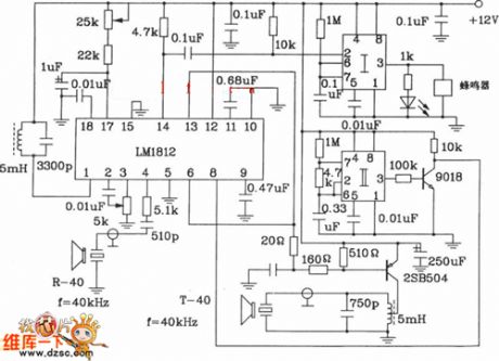
Car reverse alarm circuit diagram is shown as below.
(View)
View full Circuit Diagram | Comments | Reading(2447)
Resonance circuit diagram
Published:2011/4/1 0:57:00 Author:Rebekka | Keyword: Resonance
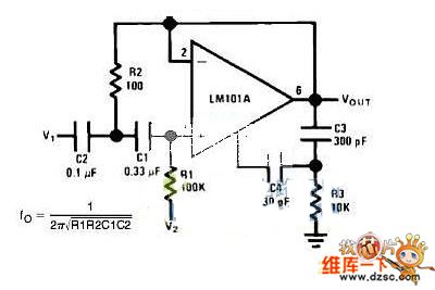
Resonance circuit diagram is shown as below.
(View)
View full Circuit Diagram | Comments | Reading(709)
Suzhou golden dragon haig bus fuse circuit diagram
Published:2011/4/1 1:44:00 Author:Rebekka | Keyword: Suzhou golden dragon haig, bus fuse
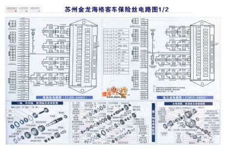
Suzhou golden dragon haig bus fuse circuit diagram is shown as below.
(View)
View full Circuit Diagram | Comments | Reading(1136)
Suzhou golden dragon haig bus chassis, heater, reading lamp circuit diagram
Published:2011/4/1 1:48:00 Author:Rebekka | Keyword: Suzhou golden dragon haig, bus fuse
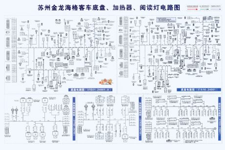
Suzhou golden dragon haig bus chassis, heater, reading lamp circuit diagram is shown as below.
(View)
View full Circuit Diagram | Comments | Reading(1506)
Four-phase stepper motor power driver circuit
Published:2011/3/22 3:37:00 Author:may | Keyword: stepper motor power driver
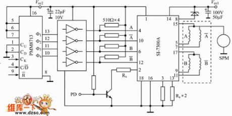
diagram: Four-phase stepper motor power driver circuit (View)
View full Circuit Diagram | Comments | Reading(1762)
Lower Power Consumption Differential Input-Differential Output Circuit
Published:2011/3/22 3:48:00 Author:may | Keyword: Lower Power Consumption, Differential Input-Differential Output
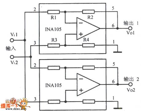
Lower Power Consumption Differential Input-Differential Output Circuit is shown in the following picture:
(View)
View full Circuit Diagram | Comments | Reading(584)
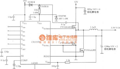
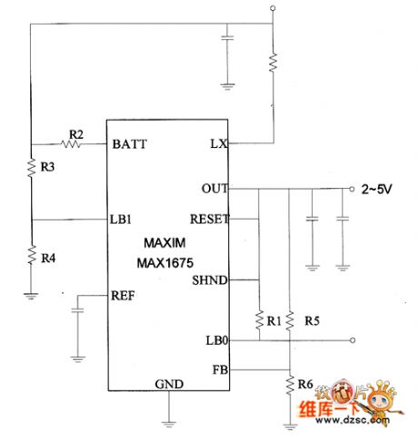
3.3V Voltage output power supply transforming circuit diagram
Published:2011/3/22 22:45:00 Author:Rebekka | Keyword: 3.3V Voltage output, power supply transforming
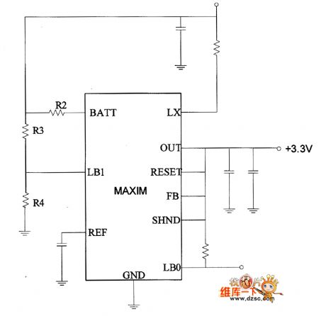
3.3V Voltage output power supply transforming circuit diagram is shown as below.
(View)
View full Circuit Diagram | Comments | Reading(764)
5V Voltage output power supply transforming circuit diagram
Published:2011/3/22 22:45:00 Author:Rebekka | Keyword: 5V Voltage output, power supply transforming
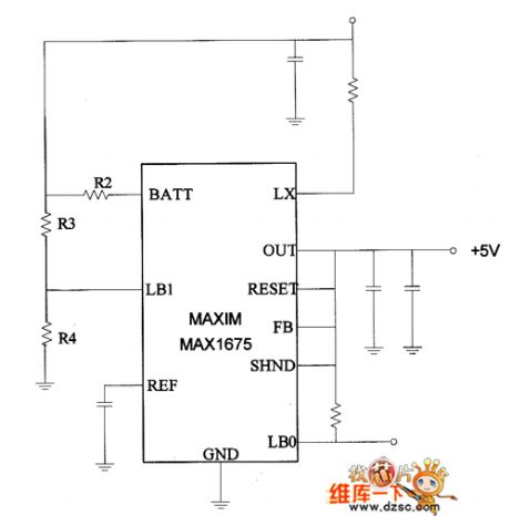
5V Voltage output power supply transformingcircuit diagram is shown as below.
(View)
View full Circuit Diagram | Comments | Reading(522)
Adjustable output power supply converting circuit diagram
Published:2011/3/22 22:42:00 Author:Rebekka | Keyword: Adjustable output, power supply converting
Adjustable output power supply converting circuit diagram is shown as below.
(View)
View full Circuit Diagram | Comments | Reading(595)
150W UPS Circuit diagram
Published:2011/3/22 22:40:00 Author:Rebekka | Keyword: 150W UPS
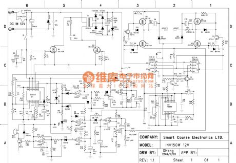
150W UPS Circuit diagram is shown as below.
(View)
View full Circuit Diagram | Comments | Reading(13022)
Digital set type standard power supply circuit(CD4516, μA723C)diagram
Published:2011/3/22 21:55:00 Author:Rebekka | Keyword: Digital set type, standard power supply
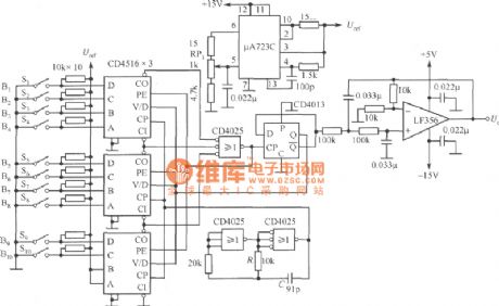
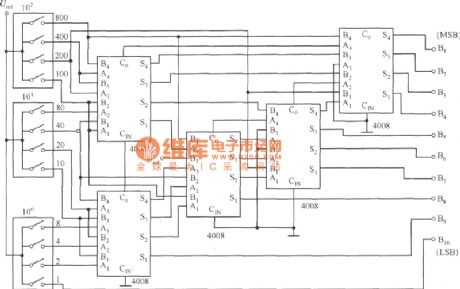
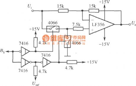
Digital set type standard power supply circuit diagram is shown as below. It is composed of digital set voltage switch(S1~S10), digital set type PWM circuit(CD4516, CD4025 and CD4013), smoothing PWM signal filter(LF356), clock generator(CD4025) and reference voltage source. Output voltage is set by Sl~S10, setting code is binary code. RPl is used for full-scale adjustment. Output voltage Uo will be adjusted to 10.23V when the digital input are all l. Filter gains 2 times(6dB), therefore, Uref is the half of 10.23V, voltage setting step is 10mV. To use the BCD-Binary number conversion circuit figure shown below when you use digital switch BCD code to set voltage. At this time, Uo is set to 3-digit display. The output voltage is 9.99V when the step voltage is 10mV.
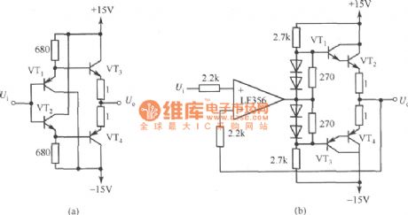
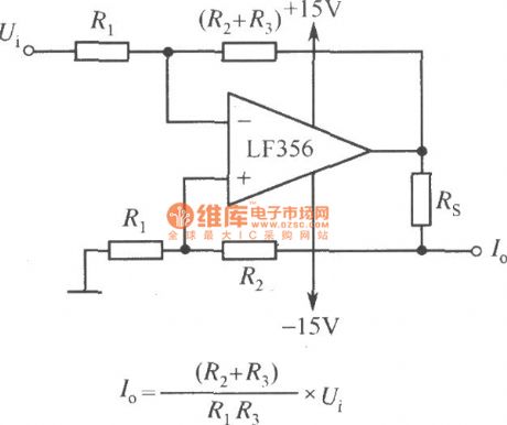
If you want to convert the polarity of output voltage, you can use the circuit diagram shown as below. The output Uo is positive voltage when Bs is 0; The output Uo is negative voltage when Bs is l. If you want to increase output power, you can use PA shown as the figure. But ±l5V power supply needs enough output power. If you want to change standard voltage into standard current source, you can add constant current circuit shown as the figure.
Output positive and negative voltage polarity converting circuit diagram:
PA circuit diagram:
Constant current circuit disgram:
(View)
View full Circuit Diagram | Comments | Reading(2851)
| Pages:12/13 12345678910111213 |
Circuit Categories
power supply circuit
Amplifier Circuit
Basic Circuit
LED and Light Circuit
Sensor Circuit
Signal Processing
Electrical Equipment Circuit
Control Circuit
Remote Control Circuit
A/D-D/A Converter Circuit
Audio Circuit
Measuring and Test Circuit
Communication Circuit
Computer-Related Circuit
555 Circuit
Automotive Circuit
Repairing Circuit