
Other Circuit
Index 2
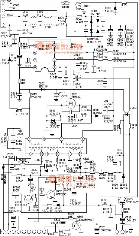
the absolutely useful switch power supply :the C7428 power supply(A4)
Published:2011/8/20 2:20:00 Author: | Keyword: absolutely useful, switch power supply
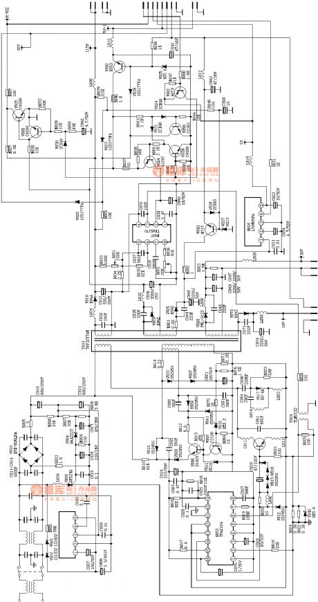
View full Circuit Diagram | Comments | Reading(794)
the power supply of A3(A4)
Published:2011/8/20 2:20:00 Author: | Keyword: power supply
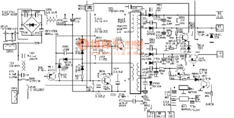
View full Circuit Diagram | Comments | Reading(748)
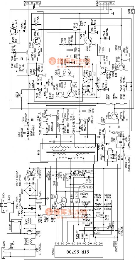
the absolutely useful switch power supply:the SONY KV2185 power supply(A4)
Published:2011/8/20 2:22:00 Author: | Keyword: absolutely useful , switch power supply
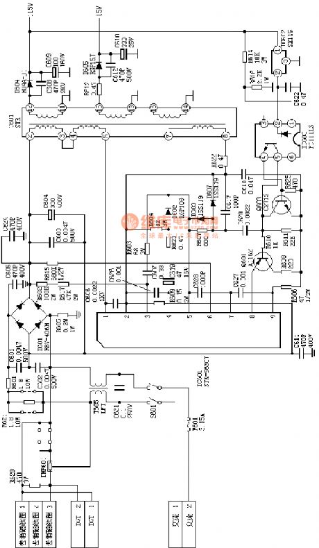
View full Circuit Diagram | Comments | Reading(700)
the absolutely useful switch power supply:the SONY KV2184 power supply(A4)
Published:2011/8/20 2:21:00 Author: | Keyword: absolutely useful, switch power supply
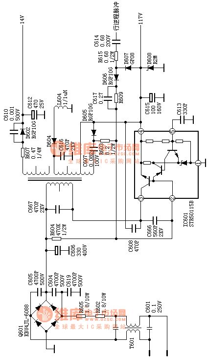
View full Circuit Diagram | Comments | Reading(939)
the absolutely useful switch power supply:the sony F29 power supply(A4)
Published:2011/8/20 2:21:00 Author: | Keyword: absolutely useful , switch power supply

View full Circuit Diagram | Comments | Reading(627)
the absolutely useful switch power supply:the Ix0689 power supply(A4)
Published:2011/8/20 2:21:00 Author: | Keyword: absolutely useful , switch power supply
View full Circuit Diagram | Comments | Reading(746)
the absolutely useful switch power supply :the D2902 power supply(A4)
Published:2011/8/20 2:21:00 Author: | Keyword: absolutely useful, switch power supply
View full Circuit Diagram | Comments | Reading(662)
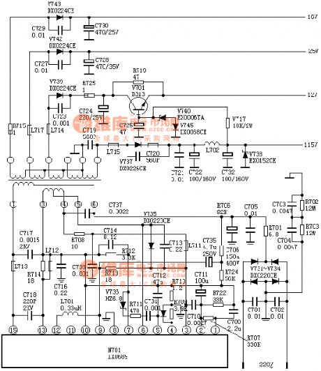
the absolutely useful switch power supply :the C7458 power supply(A4)
Published:2011/8/20 2:21:00 Author: | Keyword: absolutely useful , switch power supply
View full Circuit Diagram | Comments | Reading(702)
Servo Circuit
Published:2011/9/3 10:31:00 Author:Zoey | Keyword: Servo Circuit
Following picture shows the servo circuit, this switched circuit uses μA795 Analog multiplier and μA741 operational amplifier to produce AC error signals, and then drives the two-phase servo electronic machine, the direct input signal will be added to pin9,and AC signal will be added to pin 4 via R1 and C1, servo position signal will be added to pin 12. The multiplier takes the signal margin of pin 9 and pin 12 and multiply it by signals on pin 4, then input the value to operational amplifier from pin 14. As soon as actions of the servo electronic machine equalize voltage on pin 9 and pin 12, the system will turn to be 0. (View)
View full Circuit Diagram | Comments | Reading(668)
Maintenance Circuit of Beijing Cherokee BJ2021 Light Off-road Vehicle AC Generator
Published:2011/8/14 7:37:00 Author:Michel | Keyword: Cherokee, Light Off-road Vehicle, AC Generator, Maintenance Circuit
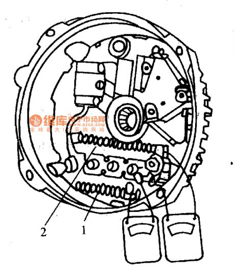
AC Generator Maintance
Beijing Cherokee uses ko-remy company ac generators, the output current is 56A, maximum output current is 61A.It uses V type more pulley groove.First, rotor.Its structure is similar to domestic ac generator rotor winding resistance and magnetic field is 2.2-3.0 ℃ Ω (When it is 27℃). Second,Stator. Three-phase stator winding is connected in triangular.Third,bridge rectifiers. As a separate parts,it is composed of six diodes.And if one diode is damaged, the rectifier assembly should be replaced.Inspection of the rectifier is shown as figure 1.The multimeter electric block is used to record the resistance value.The two touch needles touch one of the insulation heat sheet 2 and three winding.The other two winding should have the same result according to the above steps, or the diodes are damaged.
(View)
View full Circuit Diagram | Comments | Reading(963)
Beijing Cherokee BJ2021 Light Off-road Vehicle Starter Parameter Circuit
Published:2011/8/14 8:22:00 Author:Michel | Keyword: Cherokee, Off-road Vehicle, Starter Parameter Circuit
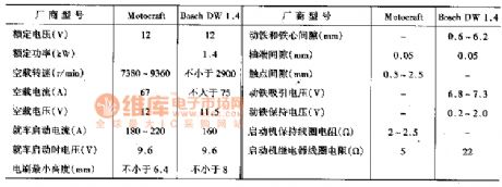
It uses DW1·4 electromagnetic control type and permanent magnet decelerating starter produced by Germany Bosch company.It uses three permanent magnets to replace the magnetic field winding and the core.It adds one level planetary gear reducer,which greatly reduces the volume and quality of starter.The starter's relative parameter are shown as table 1.
Tabke 1:Starter Parameter (View)
View full Circuit Diagram | Comments | Reading(634)
Fusible Line Circuit of Beijing Cherokee Light Off-road Vehicle
Published:2011/8/14 8:06:00 Author:Michel | Keyword: Cherokee, Light Off-road Vehicle, Fusible Line Circuit
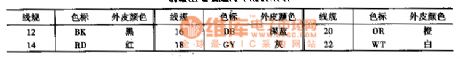
Third, Fusible Line
The fusible line protects the line in a circuit system when it is short-circuit.The color code of the fusible line stands for its specification(It is shown as table 26-7).When the fusible line is broken,we have to find out the fault reason.After the fault is completely excluded and it starts to work as usual,the line can be replaced by the same specification fusible line with polyethylene insulation sleeve.
Table: Fusible Line Circuit of Beijing Cherokee Light Off-road Vehicle (View)
View full Circuit Diagram | Comments | Reading(581)
Benchmark Voltage Source Circuit of Zero Temperature Coefficient
Published:2011/7/26 0:01:00 Author:Michel | Keyword: Temperature Coefficient, Voltage Source Circuit
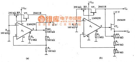
Picture a and b are the benchmark voltage source circuits of zero temperature coefficient.Zero temperature coefficient of benchmark voltage chooses the work point of field effect transistor according to zero temperature coefficient points of UGS-ID characteristic curve. It uses the voltage drop of both ends,which makes the constant current diode of zero temperature coefficient work.Operational amplifier A1 (LM4250) is the same phase work state and its work current is determined by R4.RP1 is used to set benchmark voltage temperature coefficient, it can be chosen between in positive,negative and zero.RP2 is used to adjust the voltage slightly.All the resistor in the circuit needs to choose metalfilmresistor with good temperature characteristic.Picture (b) is different from picture (a) and its A1 input end is connected with VT2 and there are two kinds of output voltgae.
(View)
View full Circuit Diagram | Comments | Reading(733)
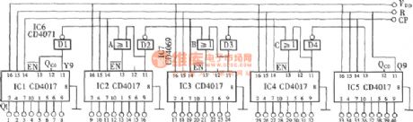
The random system output circuit composed of CD4017 (1)
Published:2011/8/12 10:43:00 Author:qqtang | Keyword: random system, output circuit
View full Circuit Diagram | Comments | Reading(956)
Voltage regulator DC-DC circuit and power supply monitor pins introduction and main features TA8001S constant voltage regulator
Published:2011/8/17 20:09:00 Author: | Keyword: Voltage regulator, power supply monitor, pins introduction, main features, constant voltage regulator
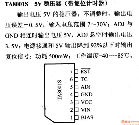
TA8001S constant voltage regulator
Its output voltage is 5 V with a difference of +/- 0.5 V. And its voltage coverage is from 7 V to 30 V. When ADJ is connected to GND, its output voltage is 5 V and when ADJ is suspended in midair, the output voltage is 3.5 V. It outputs restart signal when the power supply is connected and output voltage of 5 V lowers to 92% with the power consumption of 500mW. Its operating temperature is -40oC to +85oC. (View)
View full Circuit Diagram | Comments | Reading(706)
Voltage regulator DC-DC circuit and power supply monitor pins introduction and main features TA7900S constant voltage regulator
Published:2011/8/17 20:04:00 Author: | Keyword: Voltage regulator, power supply, main features
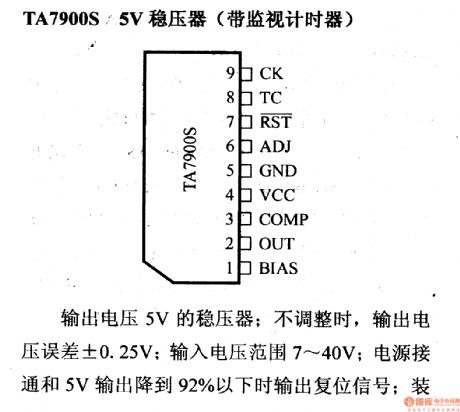
TA7900S constant voltage regulator
Its output voltage is 5 V with a difference of +/- 0.25 V. And its voltage coverage is from 7 V to 40 V. It outputs restart signal when the power supply is connected and output voltage of 5 V lowers to 92%. If the device makes mistake, the monitor will generate restart impulse with the power consumption of 500mW. Its operating temperature is -40oC to +85oC. (View)
View full Circuit Diagram | Comments | Reading(1236)
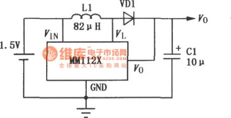
MM1126~MM1129 setting up DC-DC convertor
Published:2011/8/14 7:22:00 Author:leo | Keyword: DC-DC convertor, setting up
View full Circuit Diagram | Comments | Reading(544)
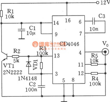
The scanning generator formed by CD4046
Published:2011/8/14 7:25:00 Author:leo | Keyword: Scanning, generator
View full Circuit Diagram | Comments | Reading(977)
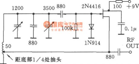
The imporved hartley circuit
Published:2011/8/17 20:23:00 Author: | Keyword: Hartley circuit
View full Circuit Diagram | Comments | Reading(559)
Voltage regulator DC-DC circuit and power supply monitor pins introduction and main features TA8505 power supply monitoring circuit
Published:2011/8/17 20:20:00 Author: | Keyword: Voltage regulator, power supply monitor, pins introduction and main features, power supply monitoring circuit
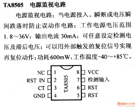
TA8505 power supply monitoring circuit When power supply is connected, cut off or voltage changes suddenly, the monitoring circuit will protect the circuit. Its operating voltage is from 1.8 V to 36 V with the output current of 30mA. It permits you set the test voltage or back-off voltage, which can use outer restart signal to carry out restart function. It has a power consumption of 600mW and the work temperature is from -40oC to +85oC. (View)
View full Circuit Diagram | Comments | Reading(797)
| Pages:2/13 12345678910111213 |
Circuit Categories
power supply circuit
Amplifier Circuit
Basic Circuit
LED and Light Circuit
Sensor Circuit
Signal Processing
Electrical Equipment Circuit
Control Circuit
Remote Control Circuit
A/D-D/A Converter Circuit
Audio Circuit
Measuring and Test Circuit
Communication Circuit
Computer-Related Circuit
555 Circuit
Automotive Circuit
Repairing Circuit