
Other Circuit
Index 7
ELECTRONIC_COIN_TOSS
Published:2009/6/19 3:40:00 Author:May
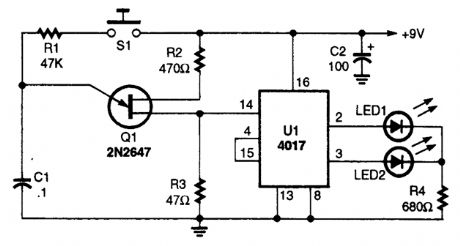
Integrated circuit U1 is connected in a two-stage counter circuit that counts one-two over and over as long as clock pulses enter pin 14 of the 4017. When the clock pulses stop, one of the LEDs will remain on, indicating the last even or odd count. Designate one LED as heads and the other as tails and you have an electronic coin flipper. (View)
View full Circuit Diagram | Comments | Reading(1076)
Z_DICE_GAME
Published:2009/6/19 3:38:00 Author:May
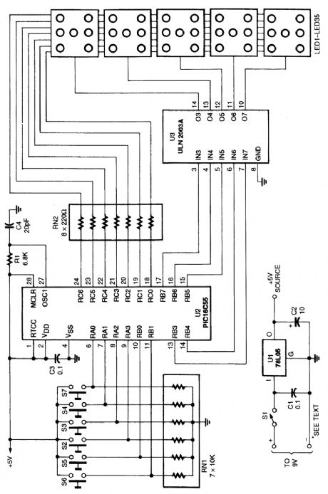
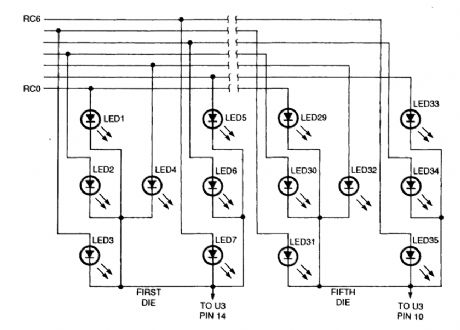
Using a microcontroller (U2) keeps the parts count and the cost of this 5-dice LED display relatively low. Z-dice uses five clusters of seven LEDs to represent the marks or pips on five dice. Buttons below each of the LED dice let the player mark a die to be rolled on the next throw. Marked dice show up as dimmed LEDs. Pressing the button to the right of the display rolls the marked dice. If the player changes his or her mind about rolling a particular die before pressing the roll button, he or she can un-mark it by pressing its button a second time. If no dice are marked at the time the player presses the roll button, then all of the dice are marked to be rolled. A second press starts them rolling, animating the LEDs of the marked dice for a second or so before displaying the results of the roll. Z-Dice doesn't count rolls or keep score, so it's still up to the players to make sure that nobody cheats!This diagram shows the wiring details of the dice display. For space and simplicity, only the first and last dice are shown. A programmed microcontroller is needed for this circuit. Refer to the original article for software. (View)
View full Circuit Diagram | Comments | Reading(1146)
FURNACE_FUEL_MISER
Published:2009/6/19 3:33:00 Author:May
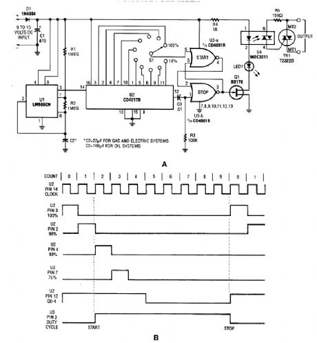
A timer (LM555CN) and decode counter is used to generate duty cycles from 10% to 100% to control the time a heating system can operate. V2 is a decode counter that can be switched from 10% to 100% duty cycle. V3A and B form a latch that drive A1, LED1, and V4. The triac TRI is used as an ac switch, in series with the thermostat that controls the heating system. (View)
View full Circuit Diagram | Comments | Reading(720)
ELECTRONIC_CRAPS_GAME
Published:2009/6/19 3:26:00 Author:May
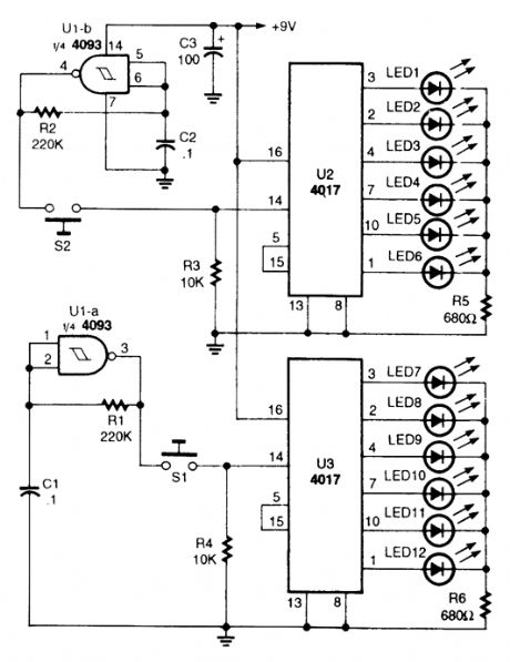
Two gates of a 4093 quad, 2-input NAND, Schrnitt-trigger CMOS IC are connected in astable-os-cillator circuits as clocks. The two 4017ICs have six LEDs connected to its first six outputs. As the clock pulses enter pin 14 of the 4017s, the ICs count from one to six over and over as long as the clock pulses are present. When S1 and/or S2 are released, one of the LEDs in each circuit will remain on, indicating a number from one to six.The circuit is set up so that you can roll the dice together by pressing S1 and S2 at the same time, or roll each die one at a time. (View)
View full Circuit Diagram | Comments | Reading(2191)
Linearization circuit of thermistance
Published:2011/5/6 1:21:00 Author:May | Keyword: Linearization, thermistance
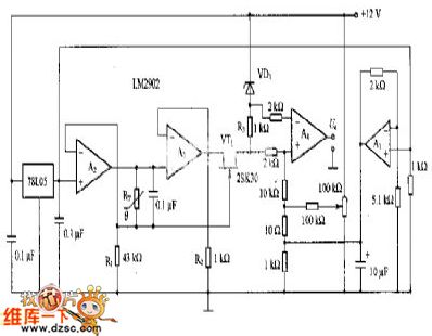
This diagram is Linearization circuit of thermistance.
In the circuit, it also is constant flow source. Its non-inverting input end is offered reference voltage by 78LO5. The output of A2 offers constant current for thermistance RT. This current is connected ground through R1. The value of constant current is determined by R1.
If RT is 5kΩ, constant current is 120μA when the voltage dropping on RT must be 0.6V. This voltage dropping adds to the source of VT1 through A3 buffer. Because the grid of VT1 is connected in one side of RT, so, grid-source voltage of VT1 is the voltage on the justified of RT. The function of R2 is flowing through idle current. The output voltage of A3 can remain unchanged when source current of VT1 changes. The justified voltage of R3 and temperature is linear relation. But R3 is in the state of floating. So, differential amplifier A4 offers this voltage. The relation between output voltage Uo and temperature changes to linear relation. (View)
View full Circuit Diagram | Comments | Reading(725)
6_DIGIT_CODED_ac_POWER_SEITCH
Published:2009/6/17 3:23:00 Author:May
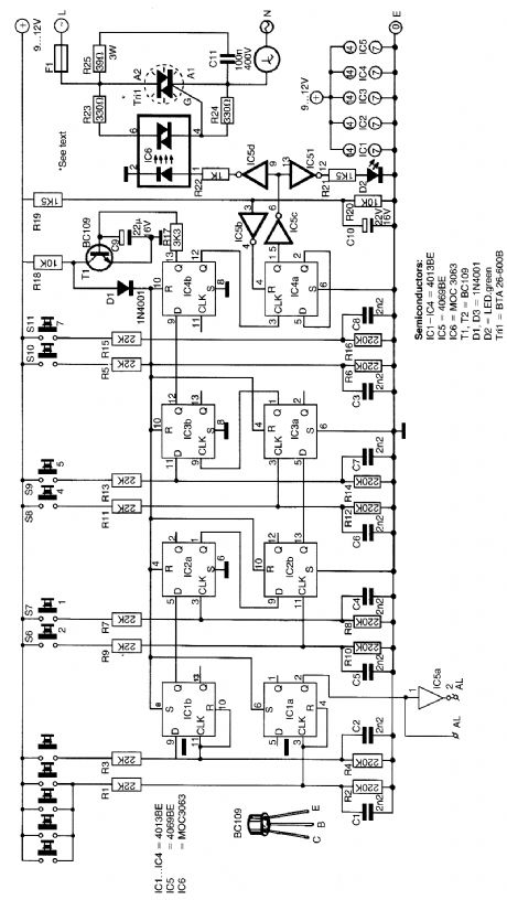
This seitch uses four CD4013 BE dual flip-flops, an inverter, and an optoisolator to drive a triac. The circuit can seitch 25-A ac load cuttrent. A standard 4×3 telephone keybord is used to enter a 6-digit code. In case of a wring cide, a signal is available to activate an alarm. The disarming method is a secret reset button that can be any number on the keyboard. (View)
View full Circuit Diagram | Comments | Reading(960)
3_CHANNEL_COLOR_ORGAN
Published:2009/6/17 3:05:00 Author:May
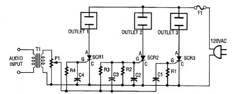
The ac line power is brought back into the circuit through F1, a protective 5-A fuse. One side of the ac line is connected to one side of each ac outlet. The other side of the ac line is connected to each SCR or silicon-controlled rectifier. Each SCR is, in turn, connected to the other side of each ac outlet.An audio signal is brought into the circuit from a stereo speaker by transformer T1. This trans-former has 500-Ω impedance on the primary and 8-Ω impedance on its secondary. Connect T1 so that the 8-Ω side is connected to the speaker and the 500-Ω side is connected to potentiometer P1.Potentiometer P1 is used as a level or sensitivity control. The signal from its wiper lead is applied to each RC filter stage. Because each SCR has a different RC (resistor/capacitor) filter on its gate lead, each will respond to different frequencies. The greater the capacitance in the filter, the lower the frequency that the SCR will respond to. (View)
View full Circuit Diagram | Comments | Reading(2003)
CAPACITANCE_MULTIPLIER
Published:2009/6/17 2:54:00 Author:May
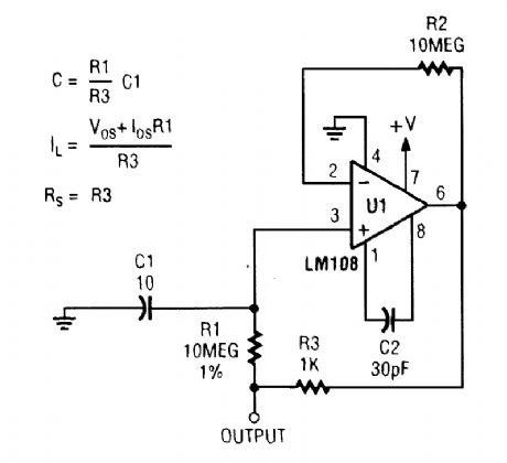
Capacitance multiplier uses the gain of an op amp to produce an effective capacitance-in this case 100,000 μF. (View)
View full Circuit Diagram | Comments | Reading(0)
μA747 dual power universal dual op amp circuit diagram
Published:2011/5/15 6:25:00 Author:Rebekka | Keyword: dual power universal, dual op amp
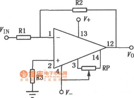
μA747 is a high gain dual op amp. The two op amps have a common bias and the negative power leads lines respectively. They have their independent functions in working mode. Its characteristics are: No external frequency compensation. It has a short-circuit protection, a wide differential mode a common mode input voltage range, low power consumption. It will not be blocked in the working mode. It can be used as integrator, summing amplifier and general feedback amplifier. The similar or direct substitution models are: CF747MT, CF747CT, CF747MD, CF747CD, CF747MJ, CF747CJ, CF747CP, SG747 and so on. The typical application circuit is shown as above. (View)
View full Circuit Diagram | Comments | Reading(898)
Southeast Ling Sheng instrument electric system circuit
Published:2011/7/20 21:40:00 Author:leo | Keyword: Instrument, electric system
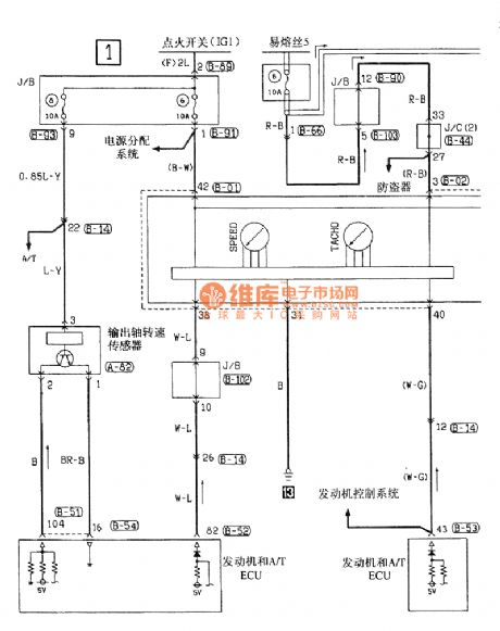
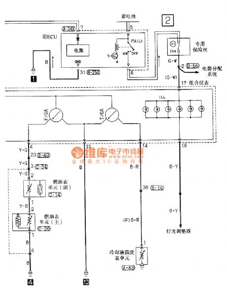
View full Circuit Diagram | Comments | Reading(793)
Southeast Ling Sheng dormer electric system circuit
Published:2011/7/20 21:50:00 Author:leo | Keyword: Dormer, electric system

View full Circuit Diagram | Comments | Reading(601)
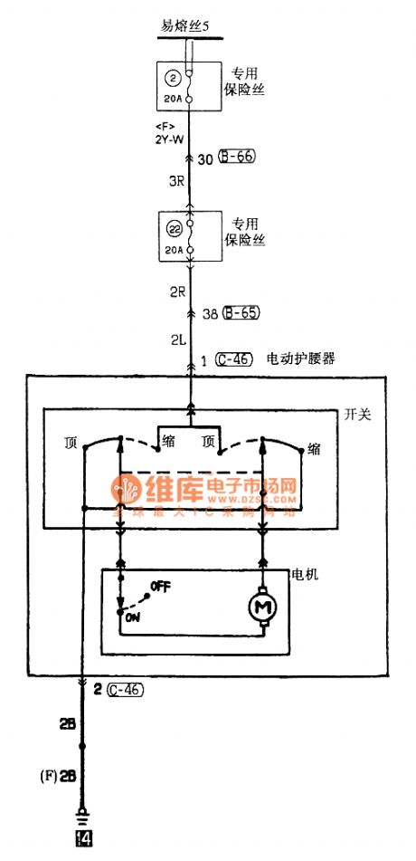
Southeast Ling Sheng waist-protecting appliance electric system circuit
Published:2011/7/20 21:54:00 Author:leo | Keyword: Waist-protecting appliance, electric system
View full Circuit Diagram | Comments | Reading(527)
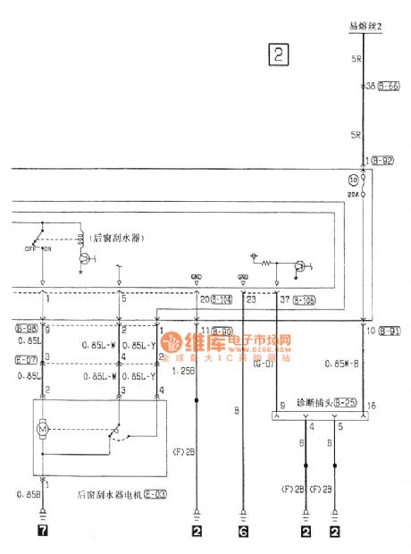
Southeast Ling Sheng rear window wiper and washer electric system circuit
Published:2011/7/20 21:58:00 Author:leo | Keyword: Rear window wiper and washer, electric system

View full Circuit Diagram | Comments | Reading(583)
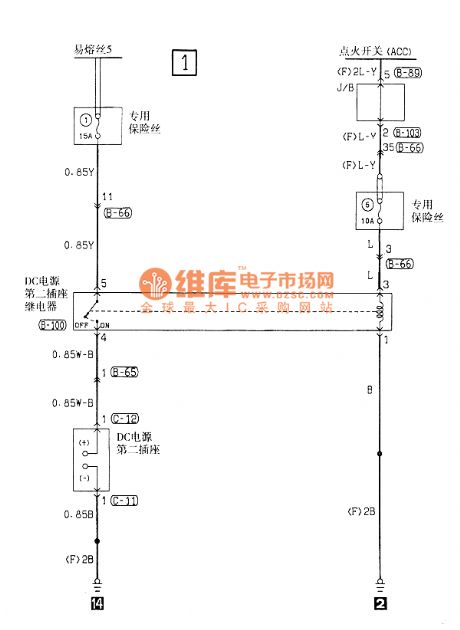
Southeast Ling Sheng the second power socket electric system circuit
Published:2011/7/20 22:01:00 Author:leo | Keyword: Power socket, electric system
View full Circuit Diagram | Comments | Reading(541)
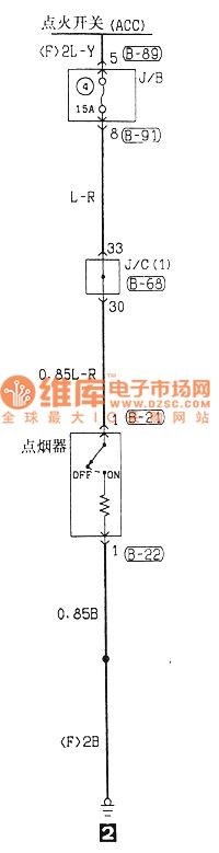
Southeast Ling Sheng cigarette lighter electric system circuit
Published:2011/7/20 23:32:00 Author:leo | Keyword: Cigarette lighter, electric system
View full Circuit Diagram | Comments | Reading(519)
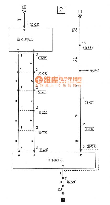
Southeast Ling Sheng car backing camera electric system circuit
Published:2011/7/20 21:21:00 Author:leo | Keyword: Car backing camera, electric system
View full Circuit Diagram | Comments | Reading(605)
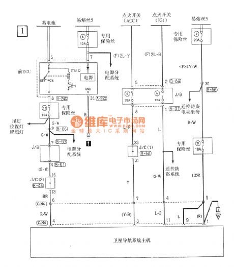
Southeast Ling Sheng mobile radio electric system circuit
Published:2011/7/20 21:24:00 Author:leo | Keyword: Mobile radio, electric system
View full Circuit Diagram | Comments | Reading(560)
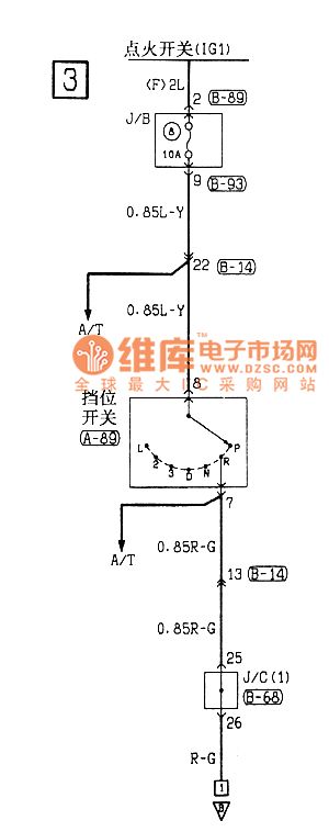
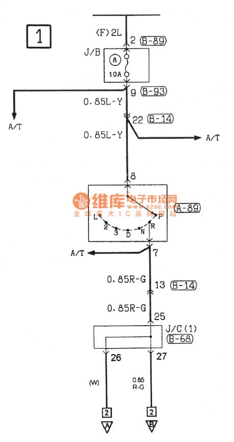
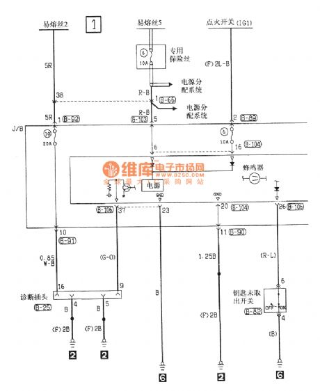
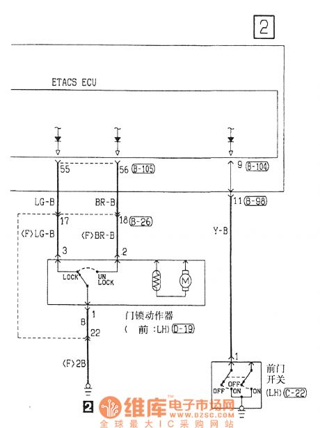
Southeast Ling Sheng key checking buzzer electric system circuit
Published:2011/7/20 21:34:00 Author:leo | Keyword: Key checking buzzer, electric system
View full Circuit Diagram | Comments | Reading(621)
STR6465 Switch Power Thick Membrane Integrated Circuit
Published:2011/7/19 11:28:00 Author:Michel | Keyword: Switch Power , Thick Membrane, Integrated Circuit
TR6465 is switch power thick membrane integrated circuit of SANKEN and it is used in ChangHong CNl1 cassette mechanism color TVs such as H25K6O,G29E6,29K19,25K18 and PF28E18.
First,Functions and Features STR6465 integrated circuit contains error control circuit, start-up circuit, switch tube (field effect power switch tube), protection circuit, and some other auxiliary functions circuit
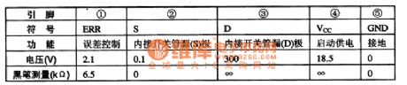
Second,Pins Functions and DataSTR6465 integrated circuit uses single inline package and its pins functions and data is shown as picture 1.
Table 1:Pins Functions and Data of STR6465 IC (View)
View full Circuit Diagram | Comments | Reading(532)
DTMF Infrared Remote Controller of LM567 Encoder
Published:2011/7/17 10:24:00 Author:Michel | Keyword: Encoder, Infrared, Remote Controller
Besides special encoder, DTMF decode still can use phase locked loop audio decoder, LM567 to decode. But there is only one kind of frequency when the frequency signal is output after the
LM567 decoding.The frequencies output by two decoders constitute one group of control signals.As shown in the picture,infrared remote control signal is transmitted by DTMF and
infrared remote control switch is composed of two LM567 decoders.The circuit consists of twelve channel coding circuit DTMF infrared remote transmitters, infrared receiving voltage amplifier, the channel signal decoder, switch controller and relay and its driving circuit. (View)
View full Circuit Diagram | Comments | Reading(806)
| Pages:7/13 12345678910111213 |
Circuit Categories
power supply circuit
Amplifier Circuit
Basic Circuit
LED and Light Circuit
Sensor Circuit
Signal Processing
Electrical Equipment Circuit
Control Circuit
Remote Control Circuit
A/D-D/A Converter Circuit
Audio Circuit
Measuring and Test Circuit
Communication Circuit
Computer-Related Circuit
555 Circuit
Automotive Circuit
Repairing Circuit