
Other Circuit
Index 8
TDAl077 Microcomputer Dialing Integrated Circuit
Published:2011/7/19 11:29:00 Author:Michel | Keyword: Microcomputer, Dialing Integrated Circuit

TDAl077 microcomputer dialing integrated circuit is often used in kinds of telephones.
One Functions and Features
TDA1077 integrated circuit contains key switch signal coder and dial signal processing circuit etc.
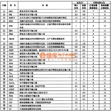
Two Pins Functions and Data
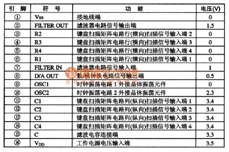
The pins function and data of TDA1077 integrated circuit are shown as table 3.
Table:Pins Functions and Data of TDA107 IC (View)
View full Circuit Diagram | Comments | Reading(561)
STR51213 Switch Power Thick Membrane Integrated Circuit
Published:2011/7/19 11:28:00 Author:Michel | Keyword: Switch Power, Thick Membrane, Integrated Circuit

STR51213 is switch power thick membrane integrated circuit of SANKEN and it is widely used in Panasonic D series big screen color TV.
One Functions and Features
STR51213 integrated circuit contains sampling signal processing circuits, incentive drive control circuit, switch tube, and other auxiliary functions circuit. Two Pins and Data
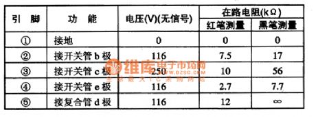
STR51213 integrated circuit uses pins single in-line package and its pins functions and data are shown as table 1.
Table:Pins Functions and Data of STR51213 IC
Note :STR51213 can substitute for STR50203 and STR50213 directly. (View)
View full Circuit Diagram | Comments | Reading(740)
STR58041 Switch Power Thick Membrane Integrated Circuit
Published:2011/7/19 11:27:00 Author:Michel | Keyword: Switch Power, Thick Membrane, Integrated Circuit
STb8041 is switch power thick membrane integrated circuit of SANKEN and it is widely used in Panasonic D series big screen color TV.
First,Functions and Features STb8041 integrated circuit contains sampling voltage processing circuit, drive control circuit, incentive and some other auxiliary functions circuit.
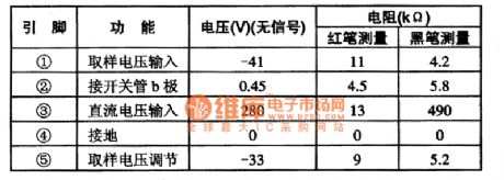
Second,Pins and DataSTb8041 uses integrated circuit uses pins single in-line and it is used in Panasonic TC-D25C type color TV.And its pins functions and data are shown as table 1.
Table 1:Pins and Data of STR58041 IC
Note:HMD9502 and KO205CE can substitute for STR5804 directly when it's broken. (View)
View full Circuit Diagram | Comments | Reading(1069)
Thermometer of Transistor Temperature Sensor
Published:2011/7/11 7:40:00 Author:Michel | Keyword: Transistor Temperature Sensor, Thermometer
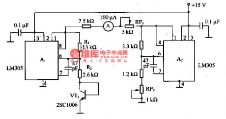
The picture is the thermometer of transistor temperature sensor. In the circuit,VT1 is transistor temperature sensor.A1 uses LM305 as voltage regulation circuit and it provides constant base current for VT1.When LM305 works in the condition that feet 6 feedback input voltage is 1.8V constantly and it is connected to VT1 base and emitter via R2 and Rz keeps the base current constant.R1/R2's change is the change of A1 output voltage.Because there is + lOmV / ℃ temperature characteristics when the output voltage of the LM305 outputs +5V and the same LM305 are used to compensate. The ammeter instruction is 0 if the RP2 is adjusted to -20℃ and the ammeter instruction is 100μA when RP1 is regulated to +80℃. (View)
View full Circuit Diagram | Comments | Reading(1084)
Nipper Shape Current Transformer
Published:2011/7/11 22:56:00 Author:Michel | Keyword: Current Transformer

SP is serial nipper shape current transformer is one kind of high accuracy current transformer.It can be used with various testing instruments, such as: multi-function watt-hour meter, recorder, oscilloscope, electric power analyzer, digital multimeter, etc .It can measure all kinds of electric parameter when the tested circuit is not cut off.SP series nipper current transformer specification has complete specifications.Users can select proper nipper current transformer according to different occasions and need.
This transformer is our newest research products.It gets consistent high praise from new and old customers since it enters the market.
Welcome to download and the news is from www.dzsc.com. (View)
View full Circuit Diagram | Comments | Reading(609)
AD521 Solar Lawn Lamp IC
Published:2011/7/13 7:39:00 Author:Michel | Keyword: Solar, Lawn Lamp, IC


AD521 is special IC which is a specially designed for solar LED lighting devices.It consists of switch type circuit, light switch circuit, overdischarging protection circuit, internal integration schottky diodes of circuits, etc.Only an external inductance can constitute solar illumination devices.AD521 uses the patent technology which LED do not glitter when it is off because of undervoltage.
(View)
View full Circuit Diagram | Comments | Reading(545)
Anti-jamming Circuit Principle Diagram with Four Analog Input Channels
Published:2011/7/12 3:32:00 Author:Michel | Keyword: Analog Input Channels, Anti-jamming Circuit, Principle Diagram

Switch input/output channels and analog input and output channels and they are interference enter channels.The object and input/output public ground lines should be removed and interference pulse should be suppressed by realizing electrical isolati to cut off this channel.The most common isolation device is photoelectric couplers, its internal structure is shown as the above picture.
Anti-jamming Circuit Principle Diagram with Four Analog Input Channels
We have to notice that:When we use photoelectric couplers to isolate input output channel,all signals(digital quantity signals,control signal,condition siganl) should be isolated and it makes both sides isolation have no electrical ties.Otherwise,the isolation is meaningless.
(View)
View full Circuit Diagram | Comments | Reading(1340)
Battery Discharging Control Indication Circuit
Published:2011/7/13 7:24:00 Author:Michel | Keyword: Battery, Discharging Control, Indication Circuit
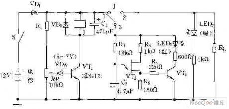
The above picture is battery discharging control indication circuit and its overdischarging circuit is composed of R1,RP and VDw.R3,C2,VT2 and VT3 constitute overdischarging indication circuit.Battery voltage R1 and RP division voltage break down VDw,which make the VT2 getfull and conduct and the 1.3 openning touch point conducts and overlaod R1 works when the switch turns on.R1 and RP can not break down VDw,which can not make VT1 get full and condcut and the relay stops working when the battery voltage decreases to 10~10.5V. (View)
View full Circuit Diagram | Comments | Reading(642)
Power Pupply, Starting and Ignition Circuit Principle Diagram of Liberation CA6400 Series Light Bus
Published:2011/7/19 9:34:00 Author:Michel | Keyword: Power Pupply, Starting, Ignition Circuit, Principle Diagram

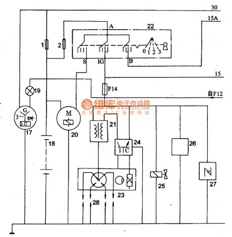
Picture: Power Pupply, Starting and Ignition Circuit Principle Diagram of Liberation CA6400 Series Light Bus
1·2一fusible line, 17一 integral ac generators,18一battery,19-rechargeable lights ,20-starter,21-ignition coil ,22-gnition switch,23-Hall type distributor ,24-ignition electronic device,25-idle block valves ,26-hot time valve ,27-automatic windshield door,28-spark plug.
(View)
View full Circuit Diagram | Comments | Reading(770)
Signal Processing,Servo and Integrated Circuit of CXA1782BQ and CXA1782BR-RF
Published:2011/7/19 11:37:00 Author:Michel | Keyword: Signal Processing, Servo, Integrated Circuit
(View)
View full Circuit Diagram | Comments | Reading(564)
Three Colors Coding Integrated Circuit of CXA1645M VCD
Published:2011/7/19 10:13:00 Author:Michel | Keyword: Three Colors, Coding Integrated Circuit
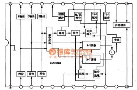
CXA1645M is three colors coding integrated circuit of VCD prodcued by SONY,which is widely used in SONY, Samsung and Sharp VCD.
First,Inner Circuit Block Diagram
CXA1645M internal includes color TV signal P/N coding system function and it can output video P/N system full TV signalor blue separation S terminal output signal as long as R, G, B three colors signal and composite synchronous pulse signal are input.The two kinds of output in IC internal have buffer amplifier and the best load is 75 Ω. CXA1645M internal does not set color coding of special color subcarrier oscillator.The special negative carrier generating circuit is used when it is used in the VCD. (View)
View full Circuit Diagram | Comments | Reading(1544)
Ultra low working voltage white LED drive circuit
Published:2011/7/17 2:24:00 Author:Fiona | Keyword: drive, Ultra low working voltage

Ultra low working voltage white LED drive circuit is shown as above:
(View)
View full Circuit Diagram | Comments | Reading(599)
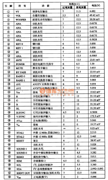
P83C266BDR Single-chip Microcomputer Integrated Circuit
Published:2011/7/17 6:32:00 Author:Michel | Keyword: Microcomputer Integrated Circuit
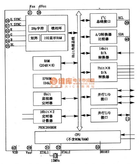
P83C266BDR is latest eight high speed digital CMOS central microcomputer monolithic integrated circuit prdoduced by Philips.It is designed for Konka series mirror TVs, such as P3486C type machine etc.
First,Fucntions
P83C266BDR integrated circuit contains the central microprocessor (CPU), electric programmable read-only memory (an EPROM), random access memory (RAM), input and output interface (I/O), l6 bit timer/counter, A/D and D/A, OSD generator, the I2C bus SCL, SDA serial interface and pulse width modulation (PWM) circuit components etc.The inside circuit of the intergrated block is shown as picture 1.
Picture 1:The Inside Circuit of Intergrated Circuit (View)
View full Circuit Diagram | Comments | Reading(903)
Digital Comb Filter Intergrated Circuit
Published:2011/7/15 4:55:00 Author:Michel | Keyword: Filter Intergrated Circuit
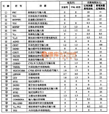
SAA4961 is a PAL/NTSC comb filter (Y/C separation) integrated circuit which is widely used in big screen and various other screen color TVs.
First,Functions and Features
SAA4961 integrated circuit is a kind of adaptive,adjust-free, PAL/NTSC format compatible comb filter.It uses discrete time, amplitude and technology to process imitation interface signal.The inner circuit of SAA4961 integrated blocks consists of delay line, filter, clock processor and signal converters etc.
Second,Pins Functions and DataSAA4961 integrated circuit uses 28 feet dual-in-line package and its pins functions and data are shown as table 1.
Table 1:Pins Functions and Data of SAA4961 (View)
View full Circuit Diagram | Comments | Reading(633)
PCMl716E DAC Decoding Intergrated Circuit
Published:2011/7/16 8:18:00 Author:Michel | Keyword: Decoding Intergrated Circuit
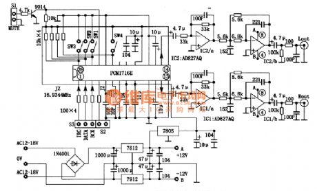
PCMl716E is senior DAC decoding integrated circuit designed by America BB company and it is designed for high-grade CD and DVD.
First,PCMl716E Functions and Features
PCMl716E adopts a modified multilevel AE which can obtain more excellent dynamic performance and reduce the chip's sensitive degree to clock jitter .It has the following main features.
(1)It is able to deal with the digital audio signal of 24 bit96KHZ specification and it also supports the the audio data of previous 16 bit 2 Obit precision.And the sampling frequency coverage is from 16 KHz to 96 KHz.
(2)Total harmonic distortion is 96 dB and dynamic range is 106 dB. (View)
View full Circuit Diagram | Comments | Reading(834)
DC-DC Optoelectronic Isolator Circuit
Published:2011/7/11 23:57:00 Author:Michel | Keyword: Optoelectronic Isolator Circuit
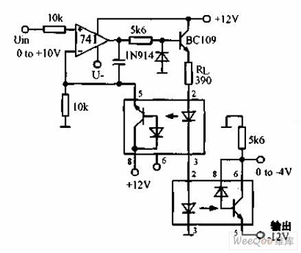
The above picture is DC-DC optoelectronic isolator circuit.The circuit is used to produce input isolation for silicon controlled converter. The above photoelectric isolator constitutes a negative feedback for the op-amp and the following photoelectric isolator completes the photoelectric signal transmission.And transmission nonlinear is within 2%.
(View)
View full Circuit Diagram | Comments | Reading(1215)
0-10 Minutes Timer Circuit with One Second Accuracy
Published:2011/7/12 2:28:00 Author:Michel | Keyword: Timer Circuit
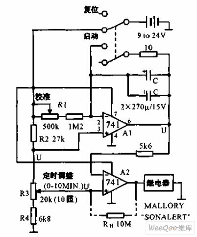

The 0-10 minutes timer circuit with one second accuracy is shown as above.It uses resistors and capacitances etc. to constitute one second accuracy timer. After it is calibrating,its accuracy has nothing to do with power voltage.Because the power supply voltage influences the charging voltage and the threshold voltage of the comparator meanwhile.The timer's delay time is CR1R3/R2. (View)
View full Circuit Diagram | Comments | Reading(654)
The Low Consumption Timer Circuit
Published:2011/7/12 2:53:00 Author:Michel | Keyword: Timer Circuit
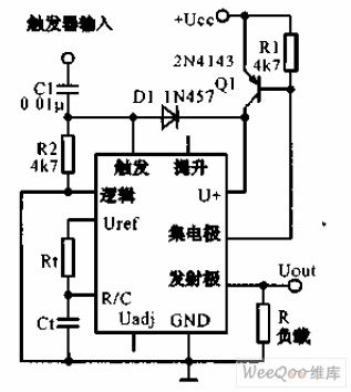
The low consumption timer uses timer IC LM122 and it provides the zero power consumption circuit in two rated cycles.The transistor Q1 stops between the two rated cycles so there is no current consumption.When 5 V or higher triggering pulse arrives and Q1 is connected and it begins to measure time. Timing time is set by the R1 and C1, its range is from a few microseconds to several hours. (View)
View full Circuit Diagram | Comments | Reading(604)
0-5 Minutes Delay Circuit of Power Frequency
Published:2011/7/14 23:39:00 Author:Michel | Keyword: Power Frequency, Delay Circuit
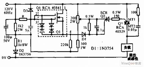
Power frequency 0-5 minutes delay circuit is shown as the above picture.This circuit uses double grid mosfet RCA40841 to constitute controlled silicon trigger circuit and the R value determines the delay time.When R is 60MΩ(LRC type CGH type resistor) and the relay time is 5 minutes and bidirectional controlled silicon can drive large current resistance loading or electrical resistance AC loading.And the error is within 10% if it is in -25~+60℃. (View)
View full Circuit Diagram | Comments | Reading(777)
The Input Loop Circuit of Amplifier Circuit
Published:2011/7/15 2:24:00 Author:Michel | Keyword: Input Loop Circuit
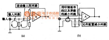
The picture (a) is the loop composed of one circle coils of the op-amp amplifier circuit input end.The magnetic will feel the electric potential when it flows through the loop and there will be noise in op-amp output part.Therefore, we need to pay attention to the components configuration and wiring,anti-noise ability can be strengthen by reducing the area of the loop, and it is shown as figure (b). (View)
View full Circuit Diagram | Comments | Reading(623)
| Pages:8/13 12345678910111213 |
Circuit Categories
power supply circuit
Amplifier Circuit
Basic Circuit
LED and Light Circuit
Sensor Circuit
Signal Processing
Electrical Equipment Circuit
Control Circuit
Remote Control Circuit
A/D-D/A Converter Circuit
Audio Circuit
Measuring and Test Circuit
Communication Circuit
Computer-Related Circuit
555 Circuit
Automotive Circuit
Repairing Circuit