
Telephone-Related Circuit
Index 3
REMOTE_TELEPHONE_BELL_RINGER
Published:2009/7/14 3:06:00 Author:May
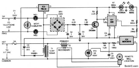
The telephone-line extension bell ringer shown will enable you to add a remote ringer in your garage or some other area where a ringing telephone cannot be heard Up to Four ringers can be used on a single telephone line, and a remote bell can be used 100 feet or more away from the unit.By substituting a light bulb for T2 and dispensing with the bell,the circuit can be made useful for the hearing-impaired.About 50 to 60 V dc is present between the tip and ring (red and green) wires of an unoccupied telephone line.Capacitor C1 blocks that dc voltage.The MOV just shunts any dialing pulses generated by a rotary phone that might be on the same line To make the phone ring,the tip and ring wires deliver an ac signal of between 90 and 130 V to the phone That ac signal is coupled through C1 to the neon lamps,NE1 and NE2 Those neon bulbs provide line isolation between the unit and the telephone line. They also neon fire (ionize) when more than 100 V is present on the phone line (in other words, during the ring signal). When they fire, they form a three-step voltage divider with the bridge rectifier. The voltage across the bridge is rectified, then filtered by R1, R2, C2, and C3, and causes Q1 to conduct. Then pins 2 and 6 of U1 go low, causing pin 3 of U1 to go high. The optoisolator and triac then turn on, applying power to the remote bell through a doorbell transformer (T2). (View)
View full Circuit Diagram | Comments | Reading(1865)
LOW_POWER_FM_TELEPHONE_BUG
Published:2009/7/14 2:29:00 Author:May
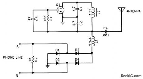
Q1 (2N3904) is an oscillator tuned to a quiet spot in the FM broadcast band. D1 through D4 (1N914) ensure proper polarity. Dc from the line powers the bug. Audio on the line causes incidental FM, which can be heard on an FM receiver tuned to the frequency of the oscillator. Warning: Use of this device for certain purposes could violate federal and/or state laws and subject the violator to prosecution. (View)
View full Circuit Diagram | Comments | Reading(2439)
TELEPHONE_BUG
Published:2009/7/14 2:35:00 Author:May
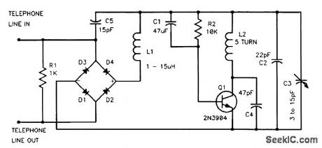
Q1 is an oscillator tuned to a quiet spot in the FM broadcast band. Dc from the line powers the bug. Diodes D1 through D4 ensure proper polarity. R1 maintains a suitable voltage drop for the bug. Audio on the line causes incidental FM, which can be heard on an FM receiver tuned to the frequency of the oscillator.Warning: Use of this device for certain purposes could violate federal and/or state laws and subject the violator to prosecution. (View)
View full Circuit Diagram | Comments | Reading(638)
Telephone electronic lock circuit diagram
Published:2011/8/4 5:07:00 Author:Rebekka | Keyword: Telephone electronic lock
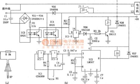
Telephone electronic lock uses the key (there is a resistance plug)inserts into the circuit and makes the periodic circuit start to oscillation. And the accuracy of the oscillation frequency can decide whether the telephone call can be opened and the receive of the external calls will not be affected. This can make sure that only the man who owns the key can uses the telephone. The circuit of the telephone electronic lock is shown as above. It is mainly composed of frequency key unlock circuit, ringing signal identifyinglock circuit, self-locking lock circuit and other components.
(View)
View full Circuit Diagram | Comments | Reading(1090)
70_V_INPUT_5_V_700_mA_TELECOM_CONVERTER
Published:2009/7/13 2:27:00 Author:May
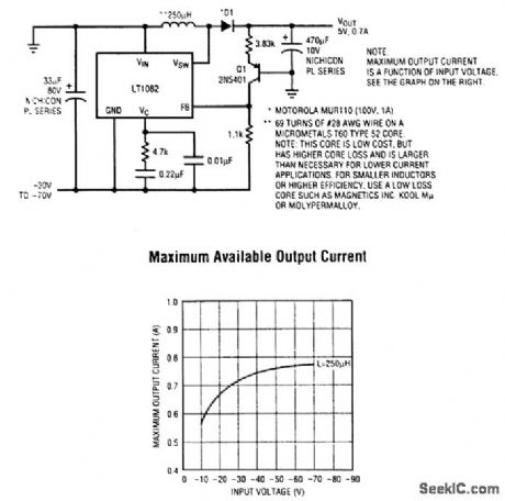
Telecom dc-to-dc conversion applications are usually complex because of the wide input voltage range of -30 to -70 V. Either big, expensive converter modules or space- and component-intensive discrete solutions are normally required to handle these higher voltages. The LT1082 contains a 1-A switch that can handle 100 V, enabling a -48-V-to-5-V converter to be designed with minimal size and cost. Features include foldback of the 60-kHz switching frequency under short-circuit condi-tions, protecting the LT1082 and power components from excessive power dissipation. The LT1082 dc-to-dc converter circuit provides up to 750 mA of output current, and the solution costs less than a modular supply of similar capabilities. (View)
View full Circuit Diagram | Comments | Reading(686)
TELEPHONE_LINE_IN_USE_INDICATOR
Published:2009/7/10 23:29:00 Author:May
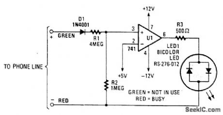
When a telephone line is not in use, about 48 V appears across the line, which drops to about 10 V or less when the line is in use. This circuit switches a bicolor LED as an indicator. (View)
View full Circuit Diagram | Comments | Reading(976)
REMOTE_RINGER
Published:2009/7/10 23:24:00 Author:May
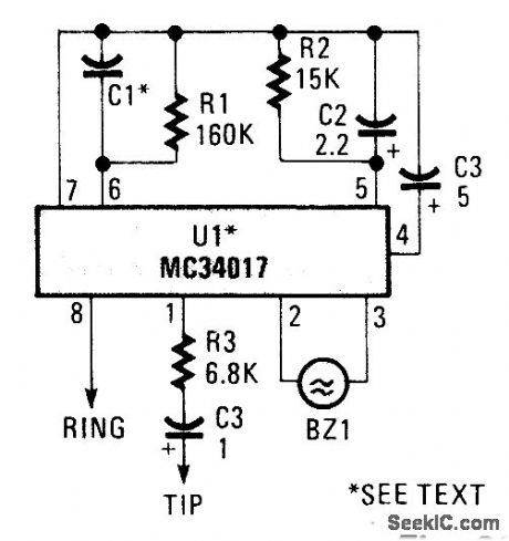
A telephone bell circuit usmg a Motorola MC34017 can be built from a few components. C1 and UI depend on the type of nng required.U1 C1 RingMC34017-1 1 000 pF 1 kHzMC34017-2 500 pF 2 kHZMC34017-3 2 000 pF 500 HzSelect the verslon of MC34017 and C1 from this table. (View)
View full Circuit Diagram | Comments | Reading(795)
TELEPHONE_VISUAL_RING_INDICATOR_1
Published:2009/7/10 23:16:00 Author:May
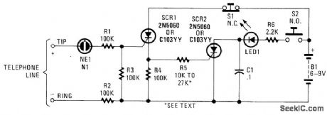
In this circuit, the ringing voltage on a telephone line causes NE-1 to break over, triggering SCR1, which in turn triggers SCR2. If a call has been received, depressing S2 will cause LED1 to light. Depressing S1 resets the circuit. This circuit has the advantage of lower battery drain because LED1 is not left on continuously after a ring signal, but only when S2 is depressed. (View)
View full Circuit Diagram | Comments | Reading(904)
EXTENSION_PHONE_RINGER
Published:2009/7/10 23:13:00 Author:May
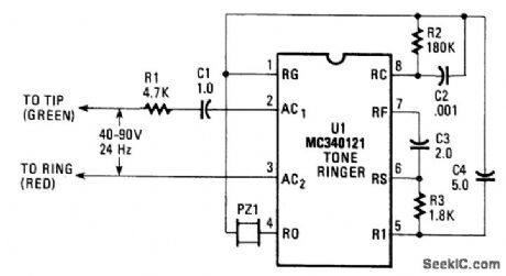
The ac ringing voltage (typically 40 to 90 V at 26 Hz) is rectified by U1, the tone-ringer IC, and is used to drive that IC's internal tone-generator circuitry. The tone-generator IC includes a relaxation oscillator (with a base frequency of 500, 1 000, or 2 000 Hz) and frequency dividers that produce the high- and low-frequency tones, as well as the tone-warble frequency. An on-board amplifier feeds a 20-Vpp signal to the transducer. (View)
View full Circuit Diagram | Comments | Reading(1350)
TELEPHONE_VISUAL_RING_INDICATOR
Published:2009/7/10 22:58:00 Author:May
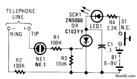
This circuit will indicate the receipt of a call. When the telephone rings,a 100- to 120-V ring signal breaks over NE1, and causes SCR1 to trigger. This causes LED1 to light until the SCR1 is turned off by depressing S1 (View)
View full Circuit Diagram | Comments | Reading(688)
THERMOCOUPLE_MULTIPLEXER
Published:2009/7/10 22:46:00 Author:May
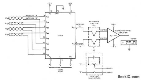
Under control of logic input, DG509 four-channel differential analog multiplexer connects selected one of four thermocouples to instrumentation amplifier driving digital or other readout. To de- room temperature, but this arrangement will be couple sensors from instrumentation amplifier, sensitive to changes in a mbient temperature.-reference junction at 0'0 can be used as shown. Analog Switches and Their Applications, Sil-Altematively, bucking voltage can be set at iconix, Santa Clara, CA, 1976, p 7-77-7-78. (View)
View full Circuit Diagram | Comments | Reading(3182)
TELL_A_BELL
Published:2009/7/10 22:44:00 Author:May
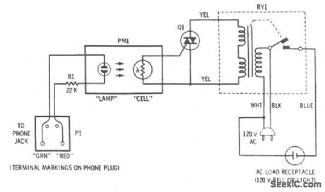
This accessory connects to phone and will activate an attention-getting 120-V bell whenever a ringing voltage appears on the phone line. The four-terminal transducer has a neon bulb close to a photocell, which are both enclosed in a light-tight tube. When the lamp is off, the cell is dark and its resistance is very high. When a ringing voltage appears on the phone line, the neon bulb glows brightly and illuminates the photocell whose resistance then drops to about 1000 Ω. The photocell is in the gate circuit of a triac that will turn on whenever the cell resistance drops. The triac is connected across the switching terminals of the isolation relay. Thus, the relay closes and applies 120 V to the output socket whenever the triac is on. (View)
View full Circuit Diagram | Comments | Reading(721)
TELEPHONE_AUTO_RECORD
Published:2009/7/10 22:42:00 Author:May
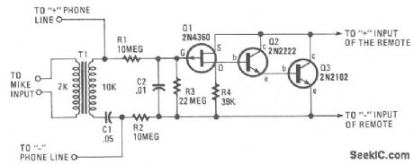
The circuit requires neither a battery nor an ac supply to make it work. Set the recorder to the record position and when the telephone is taken off the hook, the recorder starts to record everything. When the phone is on the hook, the voltage across the phone lines is about 48 Vdc. When it is taken off the hook, the line voltage drops below 10 V. When the line voltage is near 48 V, the FET is biased off and no current can flow through Q2 and Q3. When the receiver is off the hook, the voltage drops, and allows Q1 to conduct. This action turns on Q2, Q3, and the cassette recorder. (View)
View full Circuit Diagram | Comments | Reading(630)
TELEPHONE_INTERCOM
Published:2009/7/10 22:37:00 Author:May
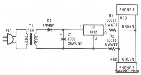
Two telephones can be used as an intercom setup with this simple power-supply arrangement. The 500-Ω resistors maintain line balance. (View)
View full Circuit Diagram | Comments | Reading(0)
TELEPHONE_SILENCER
Published:2009/7/10 22:34:00 Author:May
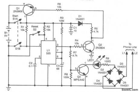
If you are busy and cannot answer or do not wish to answer your phone, this circuit will give a busy signal without you having to leave the phone off the hook. After a predetermined time, the circuit is deactivated. U1 forms an astable multivibrator that can be set for a time up to 10 minutes by values of R3 and C3. When S1A is depressed, U1 starts, and Q1 latches, which powers the circuit. At the end of a time interval determined by R3 and C3, Q2 and Q3 cut off and remove power from the circuit. During the operation, 53 throws a 150-Ω resistor across the phone line, which simulates an off-hook condition. (View)
View full Circuit Diagram | Comments | Reading(1252)
TELEPHONE_RINGER
Published:2009/7/10 22:19:00 Author:May

Using an AMI P/N S2561 IC, the circuit shown can be either powered by a battery or the telephone line in use. Output is about 50 mW. (View)
View full Circuit Diagram | Comments | Reading(0)
125_47O_K_GIVES_125_470_Hz
Published:2009/7/10 22:05:00 Author:May
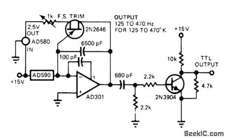
Use of AD590 current-ratioed differential-pair IC temperature transducer gives low parts count for temperature-to-frequency converter. Sensor controls AD301 opamp in relaxation oscillator, with negative-going output ramp being differentiated for driving single-transistor inverter giving TTL output.-J. Williams, Designer's Guide to: Temperature Measurement, EDN Magazine, May 20, 1977, p 71-77. (View)
View full Circuit Diagram | Comments | Reading(682)
TELEMONITOR_FOR_RECORDING_PHONE_CALLS
Published:2009/7/10 21:55:00 Author:May
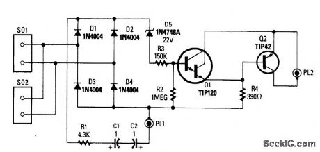
This circuit switches a tape recorder via PL2. When on-hook, D5 conducts, turns on Q1, and cuts off Q2. Ringing voltage will also cause D5 to conduct; C2 and C1 should be rated 150 V or higher. When phone is off-hook, the 10 V or so present on the line will not break down D5, and therefore Q1 is off and Q2 is biased on. PL2 connects to the remote control jack on the tape recorder. Audio is taken from PL1.Caution: Use either a battery tape recorder or an FCC/CSA/UL-approved ac adapter-powered tape recorder. This precaution is to avoid inadvertent 120 Vac on the telephone line. (View)
View full Circuit Diagram | Comments | Reading(687)
TELEPHONE_TOLL_TOTALIZER
Published:2009/7/10 21:44:00 Author:May
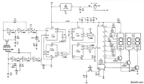
The Telephone loll Totalizer-built around two 4 518 dual synchronous up counters, a 74C925 4-digit counter, a 4 584 hex inverting buffer, and a 4081 quad 2-input AND gate-is fairly simple.Approximate toll charges can be calculated with this counter. It is started when dialing and stopped (manually) on hang-up. It is actually a counter that measures the time you are on the telephone. By calibrating it to the average cost/second of calls (get this from calculations you have done on your monthly phone bill), you can closely estimate your phone bill.The circuit consists of an oscillator running at the 100000 x frequency into the main counter (74C925). Typically, cost of telephone calls is 15 to 25 cents/minute so that the clock frequency (U1) is in the 25- to 40-kHz range. U2 and U4 with gates U3 form a ÷100000 counter. The approximate cost in dollars and cents is read out on the multiplexed display, DISP 1, 2, 3. S2 resets the counter to zero after each use. (View)
View full Circuit Diagram | Comments | Reading(2978)
TELEPHONE_TAP
Published:2009/7/7 22:55:00 Author:May
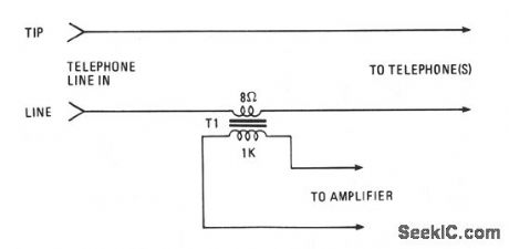
Amplify or record a telephone call with the simple circuit shown. The 8-Ω secondary winding of a min-iature transistor output transformer is connected in series with either of the telephone lines. The 1000-Ω primary winding can feed either a cassette recorder or an audio amplifier. (View)
View full Circuit Diagram | Comments | Reading(731)
| Pages:3/6 123456 |
Circuit Categories
power supply circuit
Amplifier Circuit
Basic Circuit
LED and Light Circuit
Sensor Circuit
Signal Processing
Electrical Equipment Circuit
Control Circuit
Remote Control Circuit
A/D-D/A Converter Circuit
Audio Circuit
Measuring and Test Circuit
Communication Circuit
Computer-Related Circuit
555 Circuit
Automotive Circuit
Repairing Circuit