
Magnetic Sensor
Index 2
new switch circuit of door light
Published:2011/8/20 4:16:00 Author: | Keyword: switch, door light
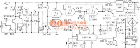
Light switch outside the door is often turned on,turned off by someone,and it is easy to damage.There is a new door light switch. This is a percussive door light switch, and has the role of the doorbell. Circuit is shown as picture, and it is mainly formed by the percussion and detection circuit, door light trigger and delay control circuit, the doorbell circuit and power supply circuit.F1 ~ F4 adopt CD4093 digital integrated circuits. Music IC adopts KD-156 model. VT1, VT2 adopt SC9014 transistor; VT3 uses SC9013 transistor; VT4 uses 2SC9012; VT5 uses 2SC8050. (View)
View full Circuit Diagram | Comments | Reading(1175)
voice operated delay lamp circuit
Published:2011/8/19 6:35:00 Author: | Keyword: voice operated, delay, lamp circuit
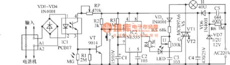
The telephone-table lamp shown in the picture can light automatically when it rings in the evening or it is off-hook,and it will extinguish after a delay of 45s when it is on-hook.Usually it can be used as a general dimming lamp without switch. And when it is used as a delay light,it will extinguish after a delay of 45s if you press the delay button.The circuit has many applications,and it is formed mainly by the optical coupling circuit, light control circuit, negative pulse generating circuit, monostable trigger circuit, thyristor switch circuit and power circuit. (View)
View full Circuit Diagram | Comments | Reading(1185)
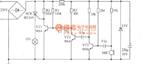
currency detector circuit
Published:2011/8/19 6:23:00 Author: | Keyword: currency detector
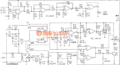
The audio alarm currency detector is used to identify the counterfeit money, this machine can remind people by sending out Attention,this is the counterfeit money, and its internal circuit is shown in the picture. It consists of magnetic track detection, watermark detection, fluorescent indicator and power supply ofaudio alarm and so on. (View)
View full Circuit Diagram | Comments | Reading(2226)
wireless alarm with multiple detective heads circuit
Published:2011/8/17 7:41:00 Author: | Keyword: wireless alarm, multiple, detective heads
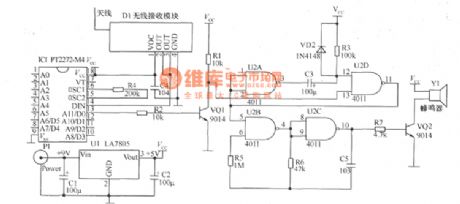
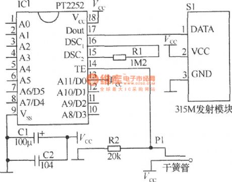
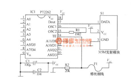
This alarm separates the detection part and alarm part,and an alarm can be with multiple detective heads.The detection part and alarm part can communicate by wireless wave. It is divided into wireless alarm receiver as well as wireless alarm detection and transmitter. The wireless alarm receiver is formed by the 315MHz wireless data receiver module, decoding IC PT2272-M4, monostabillity circuit and audio generator. Wireless alarm transmitter and detection has many detective circuits.The circuit is shown as picture.
(View)
View full Circuit Diagram | Comments | Reading(2809)
high-sensitive alarm
Published:2011/8/14 19:56:00 Author:chopper | Keyword: high-sensitive, alarm
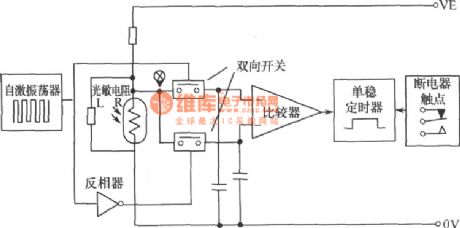
The picture shows the simplified circuit of high-sensitive alarm,and its photoresistor resistor are connected with three LDR ordinary resistors. Thus, when light varies from dark to full light,the potential range of point X is about 1/4 to 3/4 as large as power supply voltage. This potential is also added to input ends of two double contact switches.A self-excited oscillator and a grouping circuit of inverter control the switches to transform alternately,and the switching frequency is usual a few Hertz, making two capacitors charge alternately.
(View)
View full Circuit Diagram | Comments | Reading(1337)
audio monitoring system
Published:2011/8/14 20:05:00 Author:chopper | Keyword: audio, monitoring system
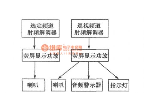
As to important program for vital period, it can adopt selected demodulator to monitor through the audio power amplifier which can display the state of the audio, and has friendly interface to get the failures timely and accurately and ensure the quality of the audio.As for programs for non-critical time,it can use automatic channel(or frequency) conversion demodulator and audio indicator and audio alarm for surveillance.
(View)
View full Circuit Diagram | Comments | Reading(1087)
thyristor drive circuit
Published:2011/8/14 20:13:00 Author:chopper | Keyword: thyristor, drive circuit
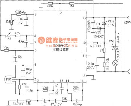
Circuit is formed mainly by the new pyroelectric infrared sensor TDH98072. The circuit assembled with the device is of the advantages like simple circuit, easy adjustment, and high reliability. The device can also assemble other control circuits, such as burglar alarm, automatic lights, automatic valves, etc.The light resistance (in the bright environment resistance) of the selected CdS photoresistor should be less than l00kΩ,and dark resistance should be greater than 3.3MΩ. Pyroelectric infrared sensor PIR can choose either a small pyroelectric sensor (with the lens, such as ANM1 type). (View)
View full Circuit Diagram | Comments | Reading(1514)
oil furnace control circuit made by frequently-used integrated package
Published:2011/8/14 20:21:00 Author:chopper | Keyword: oil furnace, control circuit, frequently-used, integrated package
The circuit is suitable for small oil furnace as a controller. The integrated package of previous small oil furnace controller is special integrated piece or single-chip microcomputer,which are difficult to buy in medium and small cities,thus the repair is difficult.The small general-purpose oil furnace controller is with reliable performance, simple structure, low cost, easy maintenance, etc.Just change the wiring, you can apply it to a variety of oil furnace. (View)
View full Circuit Diagram | Comments | Reading(1702)
omnidirectional tracking soalr electronic device
Published:2011/8/16 1:50:00 Author: | Keyword: omnidirectional tracking, soalr, electronicdevice
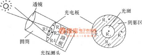
The working principle:it uses the photovoltaic solar device,and if it can not track the sun,its performance will greatly reduce. Here the device allows it to achieve full track of horizontal and vertical direction of the sun,and it will automatically reset at night.To track the sun, it must have solar probe. As shown in the picture, the solar probe of the device consists of a convex lens, five light-sensitive resistors, the control circuit board and a cylinder.
(View)
View full Circuit Diagram | Comments | Reading(1524)
inner flash circuit of camera
Published:2011/8/16 2:00:00 Author: | Keyword: flash circuit, camera
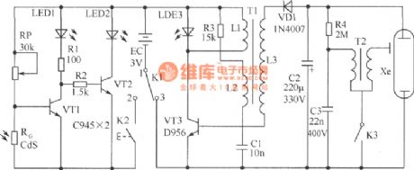
The circuit is formed by light metering circuit and flash circuit,just as shown in picture.It is suitable for POPTICS (a popular integrated camera), Franka X-500, WIZEN-860S and so on.It consists of the following circuit:(1)VT1,VT2,light metering device RG (using cadmium sulfide CdS photoresistor)form the light metering circuit. (2) VT3,C1,T1 form the inductive three-point type oscillator circuit to complete the transformation:low-voltage DC → high-voltage AC → high-voltage DC,and provide the flash with power. Component selection: VT1, VT2 use C945-type transistor;VT3 uses D965-type transistor. (View)
View full Circuit Diagram | Comments | Reading(2382)
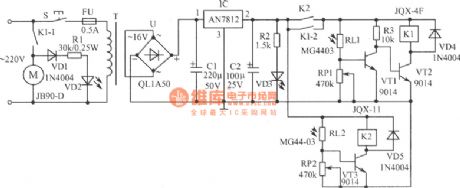
lampblack absorber automatic control circuit
Published:2011/8/16 2:10:00 Author: | Keyword: lampblack absorber, automatic control
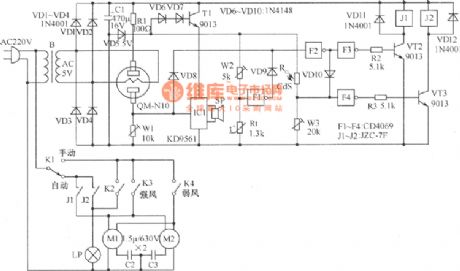
The working principle:the gas sensor and W1 in the picture form the gas detection circuit,and the 5V AC power of power transformer will heat the heating silk of the gas sensor. Inverter F1, W2, thermistor Rt form the temperature sensing circuit.The high potential signal output by two detection circuit will control the motor control circuit formed by F2, F3, R2, VT2, J1 through the isolative diode VD8, VD9 respectively. Photosensitive resistor CdS, W3, F4, R3, VT3, J2 form the lighting control circuit; IC1 is the music alarm circuit, and it is controlled by the gas detection circuit. (View)
View full Circuit Diagram | Comments | Reading(1386)
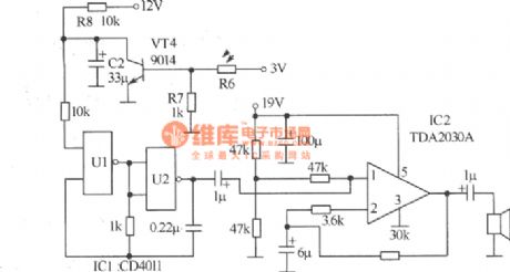
electric mixer circuit
Published:2011/8/17 7:13:00 Author: | Keyword: electric mixer
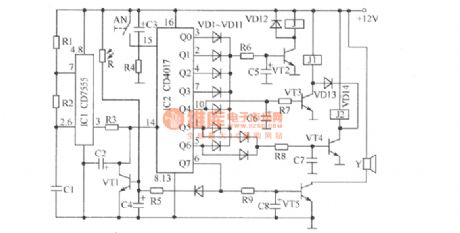
The materiel of electric mixer used in industrial and mining enterprises often has odors or dust,so the operators should not be too close.The light-operated electric mixer(or other electrical appliance) circuit shown in the picture can adopt ordinary flashlight as remote control commands, and it can control the electric mixer in 10m.The entire circuit can be put into plastic box,and it is easy to use in the field.Components selection: IC adopts AN7812 three-terminal regulator IC. VT1~VT3 use 9014 transistor. (View)
View full Circuit Diagram | Comments | Reading(1487)
neon flasher circuit of licence plate of motorcycle
Published:2011/8/17 7:29:00 Author: | Keyword: neon flasher, licence plate, motorcycle
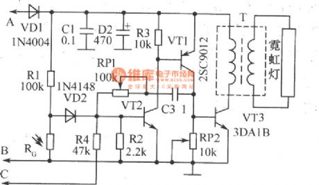
The working principle:adding the neon flasher to the licence plate of motorcycle can increase the safety of motorcycle in the evening,and it can remind the followed the vehicles, it also can flash with the tail-lamp when the motorcycle brakes.The devicecan adopt the neon tube which can surround the plate just a round as nocturnal lighting.VT1, VT2 constitute a complementary astable multivibrator, BP1, C3 determine the frequency of oscillator. (View)
View full Circuit Diagram | Comments | Reading(1330)
CdS photoresistor for electronic metering device circuit
Published:2011/7/28 22:28:00 Author:John | Keyword: CdS photoresistor, electronic metering device
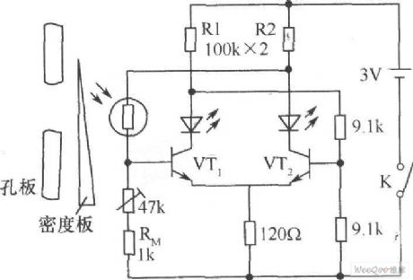
As in block cameras, CdS photoresistor can be used as electronic metering device. The light irradiation passes through the orifice in the CdS photoresistor. The MDF can be moved to achieve a balance of the circuit. When the two LED light emitting diodes are with uniform light, it is said proper to exposure. If only one lights while the other does not, it means that it is with insufficient exposure or over exposure. Thus, the MDF can be moved to achieve the correct exposure. The thermistor RM (1kΩ) in the circuit affects well for temperature compensation and compensates for error caused by temperature change of photosensitive resistor.
(View)
View full Circuit Diagram | Comments | Reading(1672)
bridge photoelectric detector composed of photosensitive resistor circuit
Published:2011/7/28 21:53:00 Author:John | Keyword: photosensitive resistor, bridge photoelectric detector
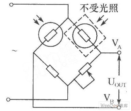
In the industrial optical measuring devices, the photosensitive resistor can be used to form the bridge photoelectric detector, just as shown in the figure. The two same models (with equivalent dark resistance) of the photoresistor are used as the bridge. One is for optical detection and the other is sealed with black tape. It is important to prevent it from being subjected to light as it is for temperature compensation. This type of bridge photodetector can be powered by DC or AC. When AC modulation, is used, its output is the AC signal, thus being able to reduce zero drift for the amplifier.
(View)
View full Circuit Diagram | Comments | Reading(1113)
3ACM And 3BCM Type Magnetic Transistor Shape Circuit
Published:2011/7/3 9:10:00 Author:Robert | Keyword: Magnetic, Transistor, Shape
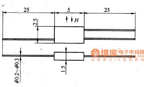
The picture shows the 3ACM and 3BCM type magnetic transistor shape circuit. (View)
View full Circuit Diagram | Comments | Reading(1066)
Resistor and capacitor (LC) circuit
Published:2011/6/19 3:44:00 Author:John | Keyword: Resistor, capacitor
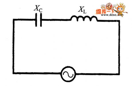
If a circuit uses both inductors and capacitors at the same time, they combine to form the inductor - capacitor (LC) resonant circuit, also known as energy storage circuit or the oscillator circuit. This circuit can be used in the radio receiver’s tuned circuits and other applications.
(View)
View full Circuit Diagram | Comments | Reading(1726)
light control switch circuit with photosensitive resistor (LDR)
Published:2011/5/24 0:28:00 Author:John | Keyword: light control switch, photosensitive resistor
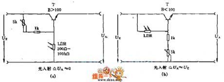
Where there is light, the transistor with photoresistor LDR in the circuit is connected in high power level or in zero level. The amplification factor of transistor β is sufficient if it is >100. And the resistance of photosensitive resistor would be between the 100Ω ~ 100KΩ. Such is arranged to be respectively corresponding to light irradiation situations and dark conditions. If it is expected to control a higher power load, it should use Darlington transistors.
(View)
View full Circuit Diagram | Comments | Reading(1782)
Homemade photo-couplers Circuit
Published:2011/5/5 2:06:00 Author:chopper | Keyword: photo-couplers
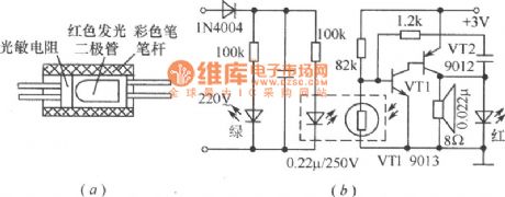
Combine the Φ55mm, red LED with photoresistance by transparent tape and put them in a pigmented penholder(black for good),and then seal both end,which has made a photo-coupler.Photo-coupler can applies to low frequency switch circuits ,just as shown in picture a.And picture b shows an outage alarm circuit adopting photo-couplers that can make an alarm if the electricity is not available.As usual,the red LED is ashine and the photo-coupler reduce the resistance of photoresistance through coupling.So,VT1 stops working,and the oscillator comprised by VT1、VT2 stops as well.When meet a commercial power cut, the resistance increases and makes VT1 connected,so that the oscillator starts to run,giving out a warning signal. (View)
View full Circuit Diagram | Comments | Reading(953)
Camera Electronic Photometering System Circuit
Published:2011/5/4 22:52:00 Author:chopper | Keyword: Camera, Electronic, Photometering System
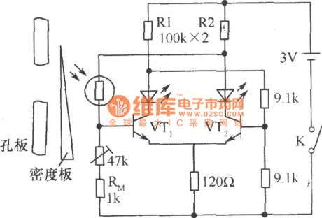
In the mid-range cameras,CdS photoresistor acts as aelectronic photometering component.When light reach the CdS photoresistor through the pore plate,move the density board to blance the circuit.And the even light sent out by two LEDs means optimum aeration.It meas underexposure or overexposure when one of the LEDs is brilliant while the other is dark.At this time,moving the density board would be a solution to get a optimum exposure. (View)
View full Circuit Diagram | Comments | Reading(662)
| Pages:2/3 123 |
Circuit Categories
power supply circuit
Amplifier Circuit
Basic Circuit
LED and Light Circuit
Sensor Circuit
Signal Processing
Electrical Equipment Circuit
Control Circuit
Remote Control Circuit
A/D-D/A Converter Circuit
Audio Circuit
Measuring and Test Circuit
Communication Circuit
Computer-Related Circuit
555 Circuit
Automotive Circuit
Repairing Circuit