
FM Signal Generating
Index
Small FM Receiver Circuit
Published:2012/9/20 21:04:00 Author:Ecco | Keyword: Small , FM Receiver
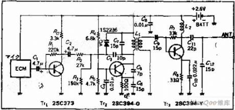
This is the most simple fm radio receiver with good performances that works great even if the sensitivity is not too high. The working principle of this fm receiver may seem a little unusual. It is made of an oscillator (T2 and T3) that is synchronized with the received frequency of T1. This transistor works as a broadband preamplifier in VHF range.The oscillator is adjusted between 87 … 108 MHz with C5. Because of the synchronization, the oscillator output will have the same frequency deviation as the received signal from the fm antenna. This deviations are caused by the broadcasted audio informations. The frequency modulated signal show up on P1 + R5. Low pass filter R6/C6 extracts the audio signal and then is amplifier by T4 … T6 and transmitted at the output through C9 capacitor.
FM Receiver Circuit Diagram
The coil details are presented in the fm receiver circuit diagram. The radio receiver is adjusted on different stations with the help of C5. P1 potentiometer is adjusted untill the best reception is obtained. If we attach an audio amplifier and a speaker then this fm receiver can be made very compact as a pocket radio.?
72 Responses to “Small FM Receiver Circuit”
(View)
View full Circuit Diagram | Comments | Reading(1072)
The function generator circuit formed by 555 timer
Published:2011/7/20 23:21:00 Author:leo | Keyword: Function generator, timer
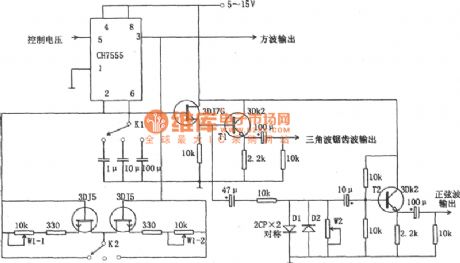
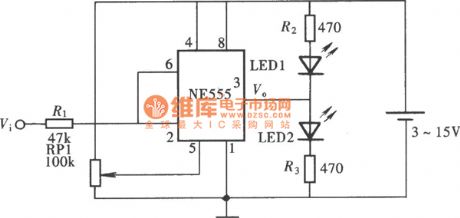
As the picture shows, it is a function generator circuit formed by 555 timer. This circuit is made up of a CH7555 timer, some transistors and RC components, which can generates triangle wave, square wave, sine wave, saw wave and swept wave. All kinds of wave have a adjustable frequency from 0.1 Hz to 100k Hz. The amplitude of vibration of square wave is from 5 V to 15 V which can drive TTL circuit. The accuracy of sine wave is higher than 3%.
(View)
View full Circuit Diagram | Comments | Reading(1640)
VHF-band FM Circuit of Variable Capacitance Diode
Published:2011/7/13 8:06:00 Author:Michel | Keyword: VHF-band, FM Circuit
Circuit's Functions
The frequency modulation FM transmitter which can be used in 76~90MHZ FM radio band, usually also it is called wireless microphone.It adopts signals via FM radio receiver.The signals can be transmitted in wireless means if we don't use the microphone but input low frequency signals.The transmitting distance can reach over 30 meters if the 60CM antenna is used.
Circuit's Work PrincipleThe TT1 makes the signal generated by the electret capacitor microphone amplify to diode's work voltage.80MHZfrequency band signal is generated by LC oscillation circuit and it is showed as the picture.The Oscillation chart L's strcture:The lead is winded to the reel with magnetic core and the oscillation frequency alters among 6~90MHZ by adjusting magnetic core. (View)
View full Circuit Diagram | Comments | Reading(2000)
(CD4069) shine type logical pen circuti of gate circuit
Published:2011/6/20 6:39:00 Author:chopper | Keyword: shine type, logical pen, gate circuit
View full Circuit Diagram | Comments | Reading(590)
acousto-optic logical pen circuit of NE555
Published:2011/6/17 6:44:00 Author:chopper | Keyword: acousto-optic, logical pen,
View full Circuit Diagram | Comments | Reading(547)
(CD4011) vocal type logical pen circuit of gate circuit
Published:2011/6/22 9:41:00 Author:chopper | Keyword: vocal type, logical pen, gate circuit
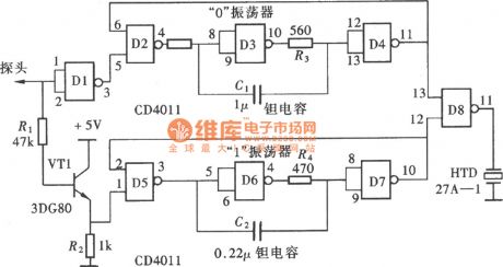
View full Circuit Diagram | Comments | Reading(597)
(CD4069) message display type logical pen circuit of gate circuit
Published:2011/6/22 9:44:00 Author:chopper | Keyword: message display type, logical pen, gate circuit
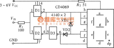
View full Circuit Diagram | Comments | Reading(541)
(CD4011) message display type logical pen circuit of gate circuit
Published:2011/6/22 9:58:00 Author:chopper | Keyword: message display type, logical pen circuit, gate circuit
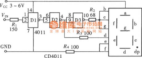
View full Circuit Diagram | Comments | Reading(592)
(CD4069) message display logical pen circuit of gate circuit
Published:2011/6/20 6:42:00 Author:chopper | Keyword: message display, logical pen, gate circuit
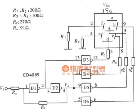
View full Circuit Diagram | Comments | Reading(605)
(CD4001)message display logical pen circuit of gate circuit
Published:2011/6/17 20:38:00 Author:chopper | Keyword: message display, logical pen, gate circuit
View full Circuit Diagram | Comments | Reading(593)
(CD4001) logical pen circuit with function of displaying the open circuit
Published:2011/6/17 6:53:00 Author:chopper | Keyword: logical pen, display the open circuit
View full Circuit Diagram | Comments | Reading(615)
logical pen of Luminous display type circuit of NE555
Published:2011/6/17 6:46:00 Author:chopper | Keyword: Luminous display, logical pen circuit
View full Circuit Diagram | Comments | Reading(535)
555 FM Circuit
Published:2011/6/9 19:09:00 Author:Michel | Keyword: 555, FM Circuit
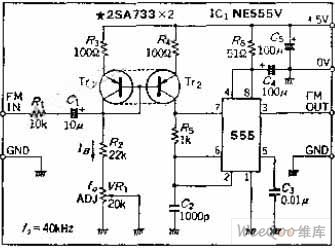
Cicuit's FunctionsThe frquency can be modulated once the charging current of 555 free-running multivibrator self- excited multivibrator ip-flop is altered.It's worth noting that it can be used as VCO if the charging current is greatly changed.This kind of oscillator's oscillation frequency is lower than 100 KHZ and the frequency of the circuit is 40 KHZ and it's close to infrared remote control frequency. This circuit also can be modulated as low frequency carrier frequency voice or data signal.
Circuit's Work PrincipleIf modulation frequency range is small, the leads 7 of the oscillating circuit can be connected to the resistance and it masses the blocking condenser stopping capacitor and then the FM moudulation can be constitituted (View)
View full Circuit Diagram | Comments | Reading(9)
The low-frequency FM generator composed of two NE566V
Published:2011/4/20 1:46:00 Author:Ecco | Keyword: low-frequency, FM , generator
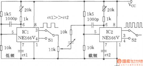
The chart shows the low-frequency FM generator composed of two NE566V. In the chart, ICl NE566Vis used for the modulation signal, IC2 works in the carrier signal. Selection ofCtlcan ensurethe modulation frequency range, selection of Ct2 could determine the center frequency of the carrier, output modulation can be used to select the square wave and triangular wave by Sl, it can realize square wave modulation and triangular wave frequency modulation.
(View)
View full Circuit Diagram | Comments | Reading(702)
FM waveform generator
Published:2011/4/17 22:14:00 Author:Ecco | Keyword: FM , waveform generator
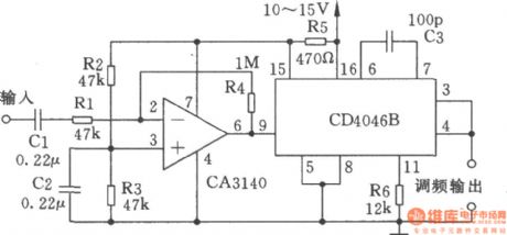
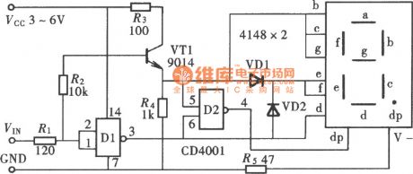
The circuit shown in Figure is the FM waveform generator which can generate 220kHz FM waveform. The internal regulator of CD40468 provides a stable supply voltage for the operational amplifier CA3140, the rated voltageis 5.4V, R5is the current limiting resistor forregulator.
(View)
View full Circuit Diagram | Comments | Reading(937)
Multi-purpose FM signal generator
Published:2011/4/12 2:54:00 Author:Ecco | Keyword: Multi-purpose , FM signal generator
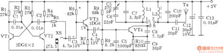
The multi-purpose FM signal generator is shown in the chart. VTl, VT2 form multivibrator, VT3 is emitter follower, which makes a frequency modulation to osicillating signal source of VT4, and sent by Tx antenna.
(View)
View full Circuit Diagram | Comments | Reading(1528)
Circuit Categories
power supply circuit
Amplifier Circuit
Basic Circuit
LED and Light Circuit
Sensor Circuit
Signal Processing
Electrical Equipment Circuit
Control Circuit
Remote Control Circuit
A/D-D/A Converter Circuit
Audio Circuit
Measuring and Test Circuit
Communication Circuit
Computer-Related Circuit
555 Circuit
Automotive Circuit
Repairing Circuit