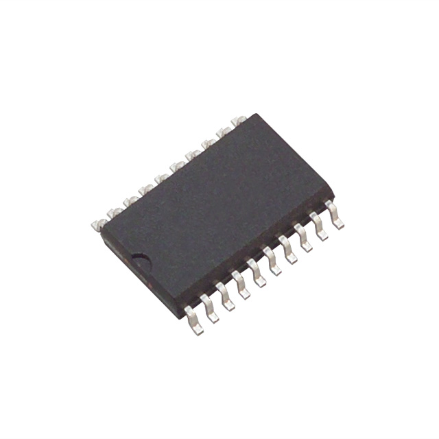
Want to post a buying lead? If you are not a member yet, please select the specific/related part number first and then fill the quantity and your contact details in the "Request for Quotation Form" on the left, and then click "Send RFQ".Your buying lead can then be posted, and the reliable suppliers will quote via our online message system or other channels soon.
The SN74ACT7200L, SN74ACT7201LA, and SN74ACT7202LA are constructed with dual-port SRAM and have internal write and read address counters to provide data throughput on a first-in, first-out (FIFO) basis. Write and read perations are independent and can be asynchronous or coincident. Empty and full status flags prevent underflow and overflow of memory, and depth-expansion logic allows combining the storage cells of two or more devices into one FIFO. Word-width expansion is also possible.
Data is loaded into memory by the write-enable (W) input and unloaded by the read-enable (R) input. Read and write cycle times of 25 ns (40 MHz) are possible with data access times of 15 ns.
These devices are particularly suited for providing a data channel between two buses operating at asynchronous rates. Applications include use as rate buffers from analog-to-digital converters in dataacquisition systems, temporary storage elements between buses and magnetic or optical memories, and queues for communication systems. A 9-bit-wide data path is provided for the transmission of byte data plus a parity bit or packet-framing information. The read pointer can be reset independently of the write pointer for retransmitting previously read data when a device is not used in depth expansion.
The SN74ACT7200L, SN74ACT7201LA, and SN74ACT7202LA are characterized for operation from 0°C to 70°C.
SN74ACT7200L Maximum Ratings
`Supply voltage range, VCC (see Note 1) . . . . . . . . . . . . . . . . . . . . . . . . . . . . . . . . . . . . . . . . . . . . . .0.5 V to 7 V `Input voltage range (any input), VI . . . . . . . . . . . . . . . . . . . . . . . . . . . . . . . . . . . . . . . . . . . . . . . . .0.5 V to 7 V `Continuous output current, IO. . . . . . . . . . . . . . . . . . . . . . . . . . . . . . . . . . . . . . . . . . . . . . . . . . . . . . . . . . . . 50 mA `Voltage applied to a disabled 3-state output . . . . . . . . . . . . . . . . . . . . . . . . . . . . . . . . . . . . . . . . . . . . . . . . .5.5 V `Operating free-air temperature range, TA . . . . . . . . . . . . . . . . . . . . . . . . . . . . . . . . . . . . . . . . . . . . .0°C to 70°C `Storage temperature range, Tstg . . . . . . . . . . . . . . . . . . . . . . . . . . . . . . . . . . . . . . . . . . . . . . .. .55°C to 125°C † Stresses beyond those listed under "absolute maximum ratings" may cause permanent damage to the device. These are stress ratings only, and functional operation of the device at these or any other conditions beyond those indicated under "recommended operating conditions" is not implied. Exposure to absolute-maximum-rated nditions for extended periods may affect device reliability.
NOTE 1: All voltage values are with respect to GND.