Want to post a buying lead? If you are not a member yet, please select the specific/related part number first and then fill the quantity and your contact details in the "Request for Quotation Form" on the left, and then click "Send RFQ".Your buying lead can then be posted, and the reliable suppliers will quote via our online message system or other channels soon.
These devices are designed to limit overvoltages on the telephone line. Overvoltages are normally caused bya.c. power system or lightning flash disturbances which are induced or conducted on to the telephone line. Asingle device provides 2-point protection and is typically used for the protection of 2-wire telecommunicationequipment (e.g. between the Ring and Tip wires for telephones and modems). Combinations of devices canbe used for multi-point protection (e.g. 3-point protection between Ring, Tip and Ground).
The protector consists of a symmetrical voltage-triggered bidirectional thyristor. Overvoltages are initiallyclipped by breakdown clamping until the voltage rises to the breakover level, which causes the device to crowbar into a low-voltage on state. This low-voltage on state causes the current resulting from the overvoltage to be safely diverted through the device. The high crowbar holding current prevents d.c. latchup as the diverted current subsides.
This TISP4xxxH3BJ range consists of thirteen voltage variants to meet various maximum system voltage levels (58 V to 275 V). They are guaranteed to voltage limit and withstand the listed international lightning surges in both polarities. These high (H) current protection devices are in a plastic package SMBJ (JEDEC DO-214AA with J-bend leads) and supplied in embossed carrier reel pack. For alternative voltage and holding current values, consult the factory. For lower rated impulse currents in the SMB package, the 50 A 10/1000 TISP4xxxM3BJ series is available.
Non-repetitive peak on-state pulse current (see Notes 2, 3 and 4) 2/10 µs (GR-1089-CORE, 2/10 µs voltage wave shape) 8/20 µs (IEC 61000-4-5, 1.2/50 µs voltage, 8/20 current combination wave generator) 10/160 µs (FCC Part 68, 10/160 µs voltage wave shape) 5/200 µs (VDE 0433, 10/700 µs voltage wave shape) 0.2/310 µs (I3124, 0.5/700 µs voltage wave shape) 5/310 µs (ITU-T K20/21, 10/700 µs voltage wave shape) 5/310 µs (FTZ R12, 10/700 µs voltage wave shape) 5/320 µs (FCC Part 68, 9/720 µs voltage wave shape) 10/560 µs (FCC Part 68, 10/560 µs voltage wave shape) 10/1000 µs (GR-1089-CORE, 10/1000 µs voltage wave shape)
ITSP
500 300 250 220 200 200 200 200 200 160 100
A
Non-repetitive peak on-state current (see Notes 2, 3 and 5) 20 ms (50 Hz) full sine wave 16.7 ms (60 Hz) full sine wave 1000 s 50 Hz/60 Hz a.c.
ITSM
55 60 2.3
A
Initial rate of rise of on-state current, Exponential current ramp, Maximum ramp value < 200 A
diT/dt
400
A/µs
Junction temperature
TJ
-40 to +150
°C
Storage temperature range
Tstg
-65 to +150
°C
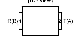
TISP4095H3BJ Connection Diagram
TISP4095H3LM Parameters
Technical/Catalog Information
TISP4095H3LM
Vendor
Bourns Inc.
Category
Circuit Protection
Package / Case
TO-92
Packaging
Bulk
Capacitance
120pF
Voltage - Breakover
95.00V
Current - Peak Pulse (8 x 20s)
300A
Current - Peak Pulse (10 x 1000s)
100A
Number of Circuits
2 - Dual
Voltage - Off State
75V
Other Names
TISP4095H3LM TISP4095H3LM
TISP4095H3LM General Description
These devices are designed to limit overvoltages on the telephone line. Overvoltages are normally caused by a.c. power system or lightning flash disturbances which are induced or conducted on to the telephone line. A single device provides 2-point protection and is typically used for the protection of 2-wire telecommunication equipment (e.g. between the Ring to Tip wires for telephones and modems). Combinations of devices can be used for multi-point protection (e.g. 3-point protection between Ring, Tip and Ground).
The protector consists of a symmetrical voltage-triggered bidirectional thyristor. Overvoltages are initially clipped by breakdown clamping until the voltage rises to the breakover level, which causes the device to crowbar into a low-voltage on state. This low-voltage on state causes the current resulting from the overvoltage to be safely diverted through the device. The high crowbar holding current prevents d.c. latchup as the diverted current subsides.
This TISP4xxxH3LM range consists of thirteen voltage variants to meet various maximum system voltage levels (58 V to 300 V). They are guaranteed to voltage limit and withstand the listed international lightning surges in both polarities. These protection devices are supplied in a DO-92 (LM) cylindrical plastic package. The TISP4xxxH3LM is a straight lead DO-92 supplied in bulk pack and on tape and reeled. The TISP4xxxH3LMF is a formed lead DO-92 supplied only on tape and reeled.