A67L7336, A67L73361, A67L8318 Selling Leads, Datasheet
MFG:AMIC Package Cooled:TQFP D/C:05+

A67L7336, A67L73361, A67L8318 Datasheet download

Part Number: A67L7336
MFG: AMIC
Package Cooled: TQFP
D/C: 05+


MFG:AMIC Package Cooled:TQFP D/C:05+
A67L7336, A67L73361, A67L8318 Datasheet download
MFG: AMIC
Package Cooled: TQFP
D/C: 05+

Want to post a buying lead? If you are not a member yet, please select the specific/related part number first and then fill the quantity and your contact details in the "Request for Quotation Form" on the left, and then click "Send RFQ".Your buying lead can then be posted, and the reliable suppliers will quote via our online message system or other channels soon.
TOP
PDF/DataSheet Download
Datasheet: A67L7336
File Size: 279396 KB
Manufacturer: AMICC [AMIC Technology]
Download : Click here to Download
PDF/DataSheet Download
Datasheet: A67L73361
File Size: 278072 KB
Manufacturer: AMICC [AMIC Technology]
Download : Click here to Download
PDF/DataSheet Download
Datasheet: A67L8318
File Size: 279396 KB
Manufacturer: AMICC [AMIC Technology]
Download : Click here to Download
The AMIC Zero Bus Latency (ZeBLTM) SRAM family employs high-speed, low-power CMOS designs using an advanced CMOS process.
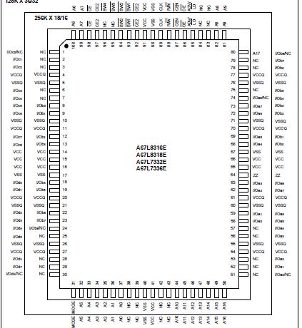
A67L8316, A67L8318, A67L7332, A67L7336 SRAMs integrate a 256K X 16, 256K X 18, 128K X 32 or 128K X 36 SRAM core with advanced synchronous peripheral circuitry and a 2-bit burst counter. These SRAMs are optimized for 100 percent bus utilization without the insertion of any wait cycles during Write-Read alternation. The positive edge triggered single clock input (CLK) controls all synchronous inputs passing through the registers.The positive edge triggered single clock input (CLK) controls all synchronous inputs passing through the registers. The synchronous inputs include all address, all data inputs, active low chip enable (CE), two additional chip enables for easy depth expansion (CE2, CE2), cycle start input (ADV/ LD ), synchronous clock enable ( CEN), byte write enables ( BW1 , BW2 , BW3 , BW4 ) and read/write (R/W).
Asynchronous inputs include the output enable (OE), clock (CLK), SLEEP mode (ZZ, tied LOW if unused) and burst mode (MODE). Burst Mode can provide either interleaved or linear operation, burst operation can be initiated by synchronous address Advance/Load (ADV/LD) pin in Low state. Subsequent burst address can be internally generated by the chip and controlled by the same input pin ADV/LD in High state.
Write cycles are internally self-time and synchronous with the rising edge of the clock input and when R/W is Low. The feature simplified the write interface. Individual Byte enables allow individual bytes to be written. BW1 controls I/Oa pins; BW2 controls I/Ob pins; BW3 controls I/Oc pins; and BW4 controls I/Od pins. Cycle types can only be defined when an address is loaded.
The SRAM operates from a +3.3V power supply, and all inputs and outputs are LVTTL-compatible. The device is ideally suited for high bandwidth utilization systems.
The AMIC Direct Bus Alternation™ (DBA™) SRAM family employs high-speed, low-power CMOS designs using an advanced CMOS process.
The A67L83161, A67L83181, A67L73321, A67L73361 SRAMs integrate a 256K X 16, 256K X 18, 128K X 32 or 128K X 36 SRAM core with advanced synchronous peripheral circuitry and a 2-bit burst counter. These SRAMs are optimized for 100 percent bus utilization without the insertion of any wait cycles during Write- Read alternation. The positive edge triggered single clock input (CLK) controls all synchronous inputs passing through the registers.The synchronous inputs include all address, all data inputs, active low chip enable (CE), two additional chip enables for easy depth expansion (CE2, CE2), cycle start input (ADV/ LD ), synchronous clock enable ( CEN), byte write enables BW1 , BW2 , BW3 , BW4 ) and read/write (R/W).
Asynchronous inputs include the output enable (OE), clock (CLK), SLEEP mode (ZZ, tied LOW if unused) and burst mode (MODE). Burst Mode can provide either interleaved or linear operation, burst operation can be initiated by synchronous address Advance/Load (ADV/LD) pin in Low state. Subsequent burst address can be internally generated by the chip and controlled by the same input pin ADV/LD in High state.
Write cycles are internally self-time and synchronous with the rising edge of the clock input and when R/W is Low. The feature simplified the write interface. Individual Byte enables allow individual bytes to be written. BW1 controls I/Oa pins; BW2 controls I/Ob pins; BW3 controls I/Oc pins; and BW4 controls I/Od pins. Cycle types can only be defined when an address is loaded.
The SRAM operates from a +3.3V power supply, and all inputs and outputs are LVTTL-compatible. The device is ideally suited for high bandwidth utilization systems.

The AMIC Zero Bus Latency (ZeBLTM) SRAM family employs high-speed, low-power CMOS designs using an advanced CMOS process.
A67L8316, A67L8318, A67L7332, A67L7336 SRAMs integrate a 256K X 16, 256K X 18, 128K X 32 or 128K X 36 SRAM core with advanced synchronous peripheral circuitry and a 2-bit burst counter. These SRAMs are optimized for 100 percent bus utilization without the insertion of any wait cycles during Write-Read alternation. The positive edge triggered single clock input (CLK) controls all synchronous inputs passing through the registers.The positive edge triggered single clock input (CLK) controls all synchronous inputs passing through the registers. The synchronous inputs include all address, all data inputs, active low chip enable (CE), two additional chip enables for easy depth expansion (CE2, CE2), cycle start input (ADV/ LD ), synchronous clock enable ( CEN), byte write enables ( BW1 , BW2 , BW3 , BW4 ) and read/write (R/W).
Asynchronous inputs include the output enable (OE), clock (CLK), SLEEP mode (ZZ, tied LOW if unused) and burst mode (MODE). Burst Mode can provide either interleaved or linear operation, burst operation can be initiated by synchronous address Advance/Load (ADV/LD) pin in Low state. Subsequent burst address can be internally generated by the chip and controlled by the same input pin ADV/LD in High state.
Write cycles are internally self-time and synchronous with the rising edge of the clock input and when R/W is Low. The feature simplified the write interface. Individual Byte enables allow individual bytes to be written. BW1 controls I/Oa pins; BW2 controls I/Ob pins; BW3 controls I/Oc pins; and BW4 controls I/Od pins. Cycle types can only be defined when an address is loaded.
The SRAM operates from a +3.3V power supply, and all inputs and outputs are LVTTL-compatible. The device is ideally suited for high bandwidth utilization systems.

Price: 4-6 USD
MT58L64L18CT-10 TQFP100

Price: 5-6.5 USD
DL-7140-211M laser tube

Price: 4-5 USD
74LVC74APG - IC FLIP FLOP D-Type POS-EDG DUAL 14TSSOP

Price: 6.5-8 USD
CYPRESS - Clock Synthesizer with Differential CPU Outputs

Price: 0.284-0.286 USD
PI5V330QEX Pericom Multiplexer Switch ICs

Price: 1-2 USD
IGBT power module, Single switch, 1200 V, Collector-emitter voltage, 430A

Price: 1-2 USD
a-Si TFT-LCD, NEC, 228.096Hmm, 560V

Price: 0.124-0.2 USD
PC354N1T - Mini-flat Package, AC Input Type Photocoupler - Sharp Electrionic Components

Price: 0.177-0.178 USD
RL1210JR51-XX-BL - Thick Film Chip Resistor Low Ohmic - TAITRON Components Incorporated

Price: 0.053-0.055 USD
STPS140A - POWER SCHOTTKY RECTIFIER - STMicroelectronics

Price: 1.45-1.5 USD
STA013 - MPEG 2.5 LAYER III AUDIO DECODER - STMicroelectronics

Price: 0.073-0.075 USD
SMBJ5347B - 5 Watt Surface Mount Silicon Zener Diodes - Micro Commercial Components
