Want to post a buying lead? If you are not a member yet, please select the specific/related part number first and then fill the quantity and your contact details in the "Request for Quotation Form" on the left, and then click "Send RFQ".Your buying lead can then be posted, and the reliable suppliers will quote via our online message system or other channels soon.
The TUSB2070 hub is a CMOS device that provides up to seven downstream ports in conformance with the USB specification, version 1.0. It supports two power source modes: bus-powered and self-powered. The hub and downstream ports share the same power source. Per the USB Specification, in the bus-powered mode, only four downstream ports (1-4) are operational, and if all seven ports are desired, the hub must be powered in the self-powered mode. The TUSB2070 hub powers down to 20 nA during the suspend operation by powering down the internal oscillator.
The TUSB2070 hub supports power switching to the downstream ports either individually or ganged. An external device or devices are required to switch power and to detect overcurrent conditions. The TUSB2070 provides outputs to control power switching and inputs to monitor any overcurrent conditions. In the ganged operation, all PWRON signals transition simultaneously and any OVRCUR input may be used.
The hub requires a 48-MHz clock signal to sample data from the upstream port and generate a synchronized 12-MHz USB clock signal. The hub supports the flexibility to use either a 48-MHz oscillator or a crystal tuned to 48-MHz. If an oscillator is used, connect its output to the XTAL1 terminal and leave the XTAL2 terminal open. An oscillator with TTL output may be used if the output does not exceed 3.6 V. For a crystal implementation, use the XTAL1 terminal as the input and the XTAL2 terminal as the feedback path to the crystal. Because the crystal is required to resonate at 48-MHz, a tuning circuit as shown in Figure 6 may be required.
USB-compliant transceivers are provided for the upstream port and all downstream ports. Every downstream port supports both full- and low-speed connection by automatically setting the slew rate according to the speed of the device attached to the port.
TUSB2070 Maximum Ratings
Supply voltage range, VCC (see Note 1) . . . . . . . . . . . . . . . . . . . . . . . . . . . . .0.5 V to 3.8 V Input voltgage range, VI . . . . . . . . . . . . . . . . . . . . . . . . . . . . . . . . . . .0.5 V to VCC + 0.5 V Output voltage range, VO . . . . . . . . . . . . . . . . . . . . . . . . . . . . . . . . . . .0.5 V to VCC + 0.5 V Input clamp current, IIK, (VI < 0 V or VI > VCC) . . . . . . . . . . . . . . . . . . . . . . . . .. . . . .±20 mA Output clamp current, IOK, (VO < 0 V or VO > VCC) . . . . . . . . . . . . . . . . . . . . .. . . . . .±20 mA Storage temperature range, Tstg . . . . . . . . . . . . . . . . . . . . . . . . . . . . . . . .65°C to 150°C NOTE 1: All voltage levels are with respect to GND.
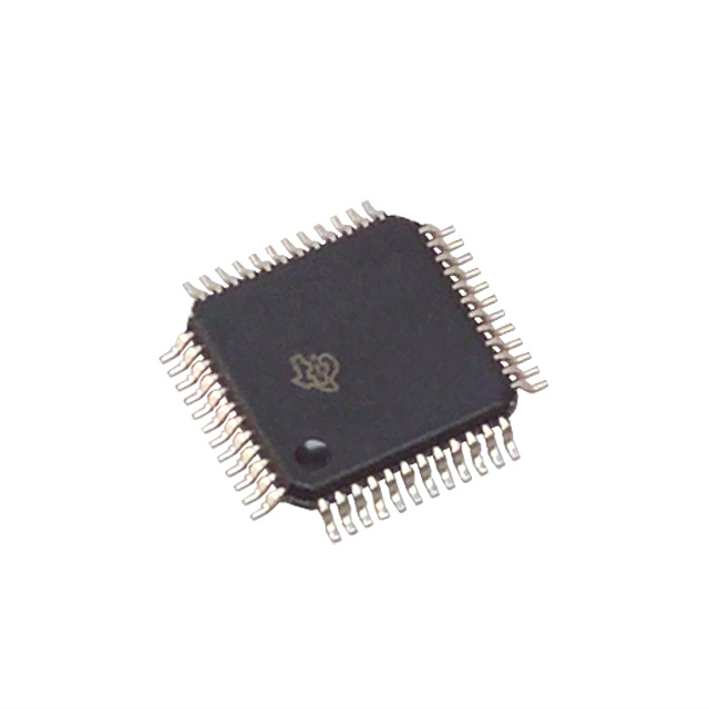
The TUSB2077A hub is a 3.3-V CMOS device that provides up to seven down stream ports in compliance with the USB version 1.1 specification. Because this device is implemented with a digital state machine instead of a microcontroller, no software programming is required. Fully compliant USB transceivers are integrated into the ASIC for all upstream and downstream ports. The downstream ports support both full-speed and low-speed devices by automatically setting the slew rate according to the speed of the device attached to the ports. The configuration of the BUSPWR terminal selects either the bus-powered or the self-powered mode. The introduction of the DP0 pull-up resistor disable pin, DP0PUR, makes it much easier to implement an on-board bus/self-power dynamic-switching circuitry. The three LED indicator control output pins also enable the implementation of visualized status monitoring of the hub and its downstream ports. With these new function pins, the end equipment vendor can considerably reduce the total board cost while adding additional product value.
The EXTMEM (Pin 47) enables or disables the optional EEPROM interface. When EXTMEM is high, the vendor and product IDs (VID and PID) use defaults, such that the message displayed during enumeration is General Purpose USB Hub. For this configuration, pin 8 functions as the GANGED input pin and the EECLK (Pin 7) is unused. If custom VID and PID descriptors are desired, theEXTMEM must be tied low (EXTMEM = 0) and a SGS Thompson M93C46 or equivalent EEPROM must be used to store the programmable VID, PID andGANGED value. For this configuration, pin 7 and pin 8 function as the EEPROM interface signals with pin 7 as EECLK and pin 8 as EEDATA respectively.
The TUSB2077A supports both bus-powered and self-powered modes. External power management devices such as the TPS2044 are required to control the 5 V-power source switching (on/off) to the downstream ports and detect over-current condition from the downstream ports individually or ganged. Outputs from external power devices provide over-current inputs to the TUSB2077A OVRCUR pins in case of an over-current condition, the corresponding PWRON pins will be disabled by the TUSB2077A. In the ganged mode, all PWRON signals transitions simultaneously, and any OVRCUR input can be used. In the nonganged mode, the PWROR outputs and OVRCUR inputs operate on a per port basis.
The TUSB2077A provides the flexibility of using either a 6-MHz or a 48-MHz clock. The logic level of the MODE terminal controls the selection of the clock source. When MODE is low, the output of the internal APLL circuitry is selected to drive the internal core of the chip. When MODE is high, the XTAL1 input is selected as the input clock source and the APLL circuitry is powered down and bypassed. The internal oscillator cell is also powered down while MODE is high. For 6-MHz operation, TUSB2077A requires a 6-MHz clock signal on XTAL1 pin (with XTAL2 for a crystal) from which its internal APLL circuitry generates a 48 MHz internal clock to sample the data from the upstream port. For 48-MHz operation, the clock cannot be generated with a crystal, using the XTAL2 output, since the internal oscillator cell only supports fundamental frequency. If low power suspend and resume are desired, a passive crystal or resonator must be used, although the hub supports the flexibility of using any device that generates a 6-MHz clock. Because most oscillators cannot be stopped while power is on, their use prohibits low-power suspend, which depends on disabling the clock. When the oscillator is used, by connecting its output to XTAL1 terminal and leaving XTAL2 terminal open, its TTL output level can not exceed 3.6 V. If a 6 MHz oscillator is used, it must be stopped at logic low whenever SUSPND is high. For crystal or resonator implementations, the XTAL1 terminal is the input and the XTAL2 terminal is used as the feedback path. A sample crystal tuning circuit is shown in Figure 7.
TUSB2077A Maximum Ratings
Supply voltage range, VCC (see Note 1) . . . . . . . . . . . . . . . . . . 0.5 V to 3.6 V Input voltgage range, VI . . . . . . . . . . . . . . . . . . . . .. . . . 0.5 V to VCC + 0.5 V Output voltage range, VO . . . . . . . . . . . . . . . . . . . . . . . 0.5 V to VCC + 0.5 V Input clamp current, IIK, (VI < 0 V or VI > VCC) . . . .. . . . . . . . . . . . . . . ±20 mA Output clamp current, IOK, (VO < 0 V or VO > VCC) . . . . . . . . . . . . . . . ±20 mA Storage temperature range, Tstg . . . . . . . . . . . . . . . .. . . . . . . . 65 to 150 Operating free-air temperature range, TA . . . . . . . . . . . . . . . . . . . . 0 to 70 † Stresses beyond those listed under "absolute maximum ratings" may cause permanent damage to the device. These are stress ratings only, and functional operation of the device at these or any other conditions beyond those indicated under "recommended operating conditions" is not implied. Exposure to absolute-maximum-rated conditions for extended periods may affect device reliability. NOTE 1: All voltage levels are with respect to GND.
TUSB2077A Features
` Universal Serial Bus (USB) Version 1.1 Compliant ` Integrated USB Transceivers ` 3.3-V Low Power ASIC Logic ` Two Power Source Modes Self-powered Mode Supporting Seven Downstream Ports Bus-powered Mode Supporting Four Downstream Ports ` All Downstream Ports Support Full-Speed and Low-Speed Operations ` Power Switching and Overcurrent Reporting is Provided Per Port or Ganged ` Supports Suspend and Resume Operations ` Suspend Status Terminal Avaliable for External Logic Power Down ` Supports Custom Vendor ID and Product ID With External Serial EEPROM ` 3-State EEPROM Interface to Allow EEPROM Sharing ` Push-Pull Outputs for PWRON Eliminate the Need for External Pullup Resistors ` Noise Filtering on OVRCUR Provides Immunity to Voltage Spikes ` Supports 6-MHz Operation Through Crystal Input or 48-MHz Input Clock ` New Functional Pins Introduced to Reduce the Board Material Cost 3 LED Indicator Control Outputs Enable Visualized Monitoring of 6 Different Hub/Port Status (HUBCFG,PORTPWR, PORTDIS) Output Pin Available to Disable External Pullup Resistor on DP0 for 15 ms After Reset or After Change on BUSPWR and Enable Easy Implementation of On-Board Bus/Self Power Dynamic Switching Circuitry ` Available in 48-Pin LQFP† Package