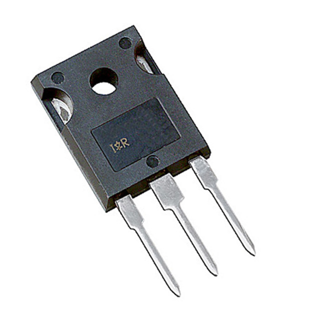
Want to post a buying lead? If you are not a member yet, please select the specific/related part number first and then fill the quantity and your contact details in the "Request for Quotation Form" on the left, and then click "Send RFQ".Your buying lead can then be posted, and the reliable suppliers will quote via our online message system or other channels soon.
•Parallel Operation for Higher Current Applications •Lower Conduction Losses and Switching Losses •Higher Switching Frequency up to 150kHz
IRGP50B60PD1 Maximum Ratings
Parameter
Max.
Units
VCES
Collector-to-Emitter Voltage
600
V
IF@ TC= 25°
CContinuous Collector Current
75
A
IF@ TC= 100°
CContinuous Collector Current
45
A
ICM
Pulsed Collector Current
150
A
ICM
Clamped Inductive Load Current
150
A
IF@ TC= 25°
40
A
IF@ TC= 100°
CDiode Continuous Forward Current
15
A
LSM
Diode Maximum Forward Current
60
A
VGE
Gate-to-Emitter Voltage
± 20
V
PD@ TC= 25°
CMaximum Power Dissipation
390
W
PD@ TC= 100°
CMaximum Power Dissipation
156
W
TJ TSTG
Operating Junction and
Storage Temperature Range
-55 to +150
°C
Soldering Temperature, for 10 sec.
300 (0.063 in. (1.6mm) from case)
IRGP50B60PD1 Features
•NPT Technology, Positive Temperature Coefficient •Lower VCE(SAT) •Lower Parasitic Capacitances •Minimal Tail Current •HEXFRED Ultra Fast Soft-Recovery Co-Pack Diode •Tighter Distribution of Parameters •Higher Reliability
IRGP50B60PD1 Typical Application
•Telecom and Server SMPS •PFC and ZVS SMPS Circuits •Uninterruptable Power Supplies •Consumer Electronics Power Supplies
IRGP50B60PD1PBF Parameters
Technical/Catalog Information
IRGP50B60PD1PBF
Vendor
International Rectifier
Category
Discrete Semiconductor Products
Input Type
Standard
Voltage - Collector Emitter Breakdown (Max)
600V
Current - Collector (Ic) (Max)
75A
Vce(on) (Max) @ Vge, Ic
2.85V @ 15V, 50A
Power - Max
390W
Mounting Type
Through Hole
Package / Case
TO-247-3 (TO-247AC, Straight Leads)
Packaging
Bag
Lead Free Status
Lead Free
RoHS Status
RoHS Compliant
Other Names
IRGP50B60PD1PBF IRGP50B60PD1PBF
IRGP50B60PD1PBF Maximum Ratings
Parameter
Max.
Units
VCES
Collector-to-Emitter Voltage
600
V
IC @ TC = 25
Continuous Collector Current
75
A
IC @ TC = 100
Continuous Collector Current
45
A
ICM
Pulse Collector Current (Ref. Fig. C.T.4)
150
A
ILM
Clamped Inductive Load Current
150
A
IF @TC = 25
Diode Continous Forward Current
40
A
IF @TC = 25
Diode Continous Forward Current
15
A
IFRM
Maximum Repetitive Forward Current
60
A
VGE
Gate-to-Emitter Voltage
±20
V
PD @ TC = 25°C
Maximum Power Dissipation
390
W
PD @ TC = 100°C
Maximum Power Dissipation
156
W
TJ TSTG
Operating Junction and Storage Temperature Range
-55 to + 150
Soldering Temperature for 10 sec.
300 (0.063 in. (1.6mm) from case)
Mounting Torque, 6-32 or M3 Screw
10 lbf`in (1.1 N`m)
IRGP50B60PD1PBF Features
• NPT Technology, Positive Temperature Coefficient • Lower VCE(SAT) • Lower Parasitic Capacitances • Minimal Tail Current • HEXFRED Ultra Fast Soft-Recovery Co-Pack Diode • Tighter Distribution of Parameters • Higher Reliability
IRGP50B60PD1PBF Typical Application
• Telecom and Server SMPS • PFC and ZVS SMPS Circuits • Uninterruptable Power Supplies • Consumer Electronics Power Supplies • Lead-Free
IRGPC20F General Description
Insulated Gate Bipolar Transistors (IGBTs) from International Rectifier have higher usable current densities than comparable bipolar transistors, while at the same time having simpler gate-drive requirements of the familiar power MOSFET. They provide substantial benefits to a host of high-voltage, highcurrent applications.
IRGPC20F Maximum Ratings
Parameter
Max.
Units
VCES
Collector-to-Emitter Voltage
600
V
IC @ TC = 25°C
Continuous Collector Current
16
A
IC @ TC = 100°C
Continuous Collector Current
9.0
ICM
Pulsed Collector Current
64
ILM
Clamped Inductive Load Current
64
VGE
Gate-to-Emitter Voltage
±20
V
EARV
Reverse Voltage Avalanche Energy
5.0
mJ
PD @ TC = 25°C
Maximum Power Dissipation
60
W
PD @ TC = 100°C
Maximum Power Dissipation
24
TJ TSTG
Operating Junction and Storage Temperature Range
-55 to + 150
°C
Soldering Temperature, for 10 sec.
300 (0.063 in. (1.6mm) from case)
Mounting torque, 6-32 or M3 screw.
10 lbf`in (1.1N`m)
IRGPC20F Features
• Switching-loss rating includes all "tail" losses • Optimized for medium operating frequency (1 to 10kHz) See Fig. 1 for Current vs. Frequency curve