Features: * MMT-licensed two-phase stepper motor compatible
* Minimal processor overhead required
* Fully integrated pointer movement and position state machine with air core movement emulation
* 4096 possible steady state pointer positions
*340° maximum pointer sweep
* Linear 4500°2
* Max pointer velocity of 400°
* Analog micro stepping (12 steps/degree of pointerIMINmovement)
* Pointer calibration and return to zero
* SPI controlled 16-bit word
* Calibratable Internal Clock
* Low Sleep mode currentPinout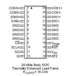 Specifications
|
Rating |
Symbol |
Value |
Limit |
|
Power Supply Voltage
Steady State |
VPWR(sus) |
-0.3 to 41 |
V |
|
Input Pin Voltage (Note15) |
VIN |
-0.3 to 7.0 |
V |
|
SIN+/- COS +/- Continuous Per Output Current (Note16) |
IOUTMAX |
40 |
mA |
|
Storage Temperature |
Tstg |
-55to150 |
°C |
|
Operating Junction Temperature |
TJunc |
-40to150 |
°C |
|
Thermal Resistance (C/W)
Ambient Junction to Lead |
qJA
qJL |
60
20 |
°C/W
°C/W |
|
ESD Voltage
Human Body Model (Note17)
Machine Model (Note18) |
VESD1
VESD2 |
2000
200 |
V
V |
DescriptionThis register allows the master to independently enable or disable the output drivers of the two gauge controllers.
SIAddress000-Power,Enable,andCalibrationRegisteris illustrated in Table 3. A write to the 33991using this register allowsthemastertoindependentlyenableordisabletheoutput drivers of the two gauge controllers as well as to calibrate the internal clock, or send a null command for the purpose of reading the status bits. This register is also used to place the 33991device into a low current consumption mode.
Each of the gauge drivers can be enabled by writing a logic [1] to their assignedaddressbits,D0andD1respectively. This feature could be useful to disable a driver if it is failing or not being used. The device can be placed into a standby current modebywritingalogic[0]tobothD0andD1.Duringthisstate, most current consuming circuits are biased off. When in the Standby mode, the internal clock will remain on.
TheinternalstatemachineutilizesaROMtableofsteptimes defining thedurationthemotorwill spendateachmicrostepas it accelerates or decelerates to a commanded position. The accuracyoftheaccelerationandvelocityofthemotorisdirectly related to the accuracy of the internal clock. Although the accuracy of the internal clock is temperature independent, the non-calibrated tolerance is +70 percent to -35 percent. The 33991devicewasdesignedwithafeatureallowingtheinternal clock to be software calibrated to a tighter tolerance of ±10 percent, using the CS pin and a reference time pulse provided by the microcontroller.
Calibration of the internal clock is initiated by writing a logic [1] to D3. The calibration pulse, must be 8 s for an internal clock speed of 1 MHz, will be sent on the CS pin immediately after the SPI word is sent. No other SPI lines will be toggled. A clock calibration is allowed only if the gauges are disabled or the pointers are not moving, indicated by status bits ST4 and ST5.
Some applications may require a guaranteed maximum pointer velocity and acceleration. Guaranteeing these maximums require the nominal internal clock frequency fall below 1 MHz. The frequency range of the calibrated clock is always below 1 MHz if bit D4 is logic [0] when initiating a calibration command followed by an 8 s reference pulse. The frequency is centered at 1MHz if bit D4 is logic [1]. Someapplicationsmayrequireaslowercalibratedclockdue toalowermotorgearreductionratio.Writingalogic[1]tobitD2 will slow the internal oscillator by one-third, leading to a situation where it is possible to calibrate at maximum 667 kHz or centered at 667 kHz. In these cases, it maybe necessaryto provide a longer calibration pulse of exactly 12 s without any indication of a calibration fault at status bit ST7. The preceding description should be the case for 1 MHz if D2 is left logic [0].
If bit D12 is logic [1] during a PECR command, the state of D11:D0isignored.Thisisreferredtoasthenullcommandand can be used to read device status without affecting device operation.

 33991 Data Sheet