74LV163

Features: *Optimized for low voltage applications: 1.0 to 3.6 V*Accepts TTL input levels between VCC = 2.7 V and VCC = 3.6 V*Typical VOLP (output ground bounce) < 0.8 V at VCC = 3.3 V, Tamb = 25° C *Typical VOHV (output VOH undershoot) > 2 V at VCC = 3.3 V, Tamb= 25° C*Synchronous counting a...

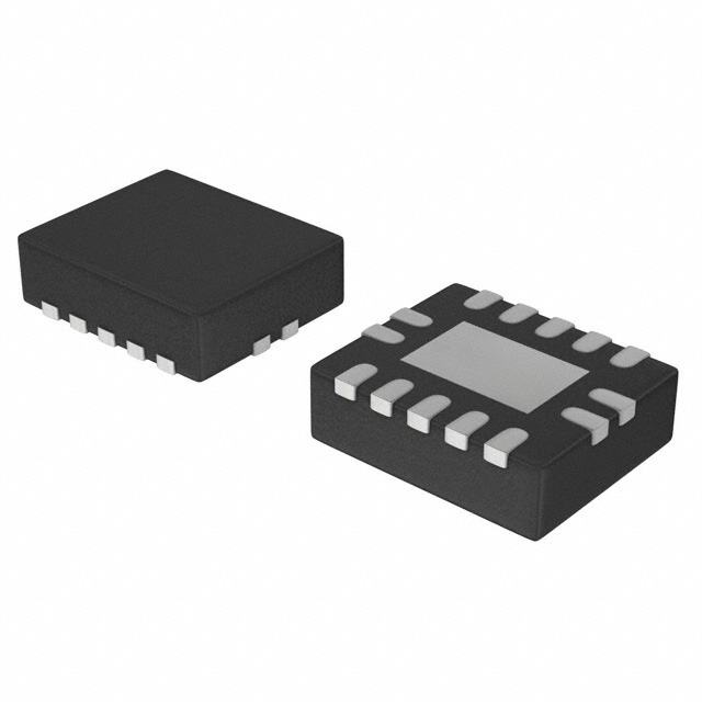
product image

74LV163 Picture
SeekIC No. : 004251144 Detail

74LV163: Features: *Optimized for low voltage applications: 1.0 to 3.6 V*Accepts TTL input levels between VCC = 2.7 V and VCC = 3.6 V*Typical VOLP (output ground bounce) < 0.8 V at VCC = 3.3 V, Tamb = 25°...

floor Price/Ceiling Price

Part Number:
74LV163
Supply Ability:
5000

Price Break

  • Qty
  • 1~5000
  • Unit Price
  • Negotiable
  • Processing time
  • 15 Days
Total Cost: $ 0.00

SeekIC Buyer Protection PLUS - newly updated for 2013!

  • Escrow Protection.
  • Guaranteed refunds.
  • Secure payments.
  • Learn more >>

Month Sales

268 Transactions

Rating

evaluate  (4.8 stars)

Upload time: 2024/4/23

Payment Methods

All payment methods are secure and covered by SeekIC Buyer Protection PLUS.

Notice: When you place an order, your payment is made to SeekIC and not to your seller. SeekIC only pays the seller after confirming you have received your order. We will also never share your payment details with your seller.
Product Details

Description


Features:

*Optimized for low voltage applications: 1.0 to 3.6 V
*Accepts TTL input levels between VCC = 2.7 V and VCC = 3.6 V
*Typical VOLP (output ground bounce) < 0.8 V at VCC = 3.3 V,  Tamb  = 25° C
*Typical VOHV (output VOH undershoot) > 2 V at VCC = 3.3 V,  Tamb= 25° C
*Synchronous counting and loading
*Two count enable inputs for n-bit cascading
*Positive-edge triggered clock
*Synchronous reset
*Output capability: standard
*ICC category: MSI


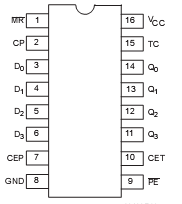
Pinout

  Connection Diagram


Specifications

SYMBOL
PARAMETER CONDITIONS
RATING
UNIT
VCC
DC supply voltage  
0.5 to +4.6
V
±IIK
DC input diode current VI < 0.5 or VI > VCC + 0.5V
20
mA
±IOK
DC output diode current VO < 0.5 or VO > VCC + 0.5V
50
mA
±IO
DC output source or sink current
standard outputs
0.5V < VO < VCC + 0.5V
25
mA
±IGND,
±ICC
DC VCC or GND current for types with
standard outputs
 
50
mA
Tstg
Storage temperature range  
65 to+150
°C
PTOT
Power dissipation per package
plastic DIL
plastic mini-pack (SO)
plastic shrink mini-pack (SSOP and TSSOP)
for temperature range: 40 to +125C
above +70°C derate linearly with 12mW/K
above +70°C derate linearly with 8 mW/K
above +60°C derate linearly with 5.5 mW/K
750
500
400
mW


Description

The 74LV163 is a low-voltage Si-gate CMOS device and is pin and function compatible with 74HC/HCT163.

The 74LV163 is a synchronous presettable binary counter which features an internal look-head carry and can be used for high-speed counting. Synchronous operation is provided by having all flip-flops clocked simultaneously on the positive-going edge of the clock (CP). The outputs (Q  to Q ) of the counters may be preset to a HIGH or 0 3 LOW level. A LOW level at the parallel enable input (PE) disables the counting action and causes the data at the data inputs (D0 to D3) to be loaded into the counter on the positive-going edge of the clock (providing that the set-up and hold time requirements for PE are met). Preset takes place regardless of the levels at count enable inputs (CEP and CET). A low level at the master reset input (MR) of the 74LV163 sets all four outputs of the flip-flops (Q  to Q ) to LOW level after the next 0 3 positive-going transition on the clock (CP) input (provided that the set-up and hold time requirements for MR are met).

This action occurs regardless of the levels at PE, CET and CEP inputs. This synchronous reset feature of the 74LV163 enables the designer to modify the maximum count with only one external NAND gate. The look ahead carry simplifies serial cascading of the counters. Both count enable inputs (CEP and CET) must be HIGH to count. The CET input is fed forward to enable the terminal count output (TC). The TC output thus of the 74LV163 enabled will produce a HIGH output pulse of a duration approximately equal to a HIGH level output of Q . This 0 pulse can be used to enable the next cascading stage. The maximum clock frequency for the cascaded counters is determined by the CP to TC propagation delay and CEP to CP set-up time, according to the following formula:


Customers Who Bought This Item Also Bought

Margin,quality,low-cost products with low minimum orders. Secure your online payments with SeekIC Buyer Protection.
Sensors, Transducers
Boxes, Enclosures, Racks
Semiconductor Modules
Fans, Thermal Management
Motors, Solenoids, Driver Boards/Modules
Power Supplies - External/Internal (Off-Board)
View more