Features: · Temperature protection provided by directly detecting the junction temperature of the IGBTs.
· Low power loss and soft switching.
· High performance and high reliability IGBT with overheating protection.
· Both P-side and N-side alarm output available.
· Higher reliability because of a big decrease in number of parts in built-in control circuit.
Specifications
|
Item |
Symbol |
Rating |
Unit |
|
Min. |
Max. |
|
Bus voltage |
DC |
VDC |
0 |
900 |
V |
| Surge |
VDC(surge) |
0 |
1000 |
V |
| Short operating |
VSC |
200 |
800 |
V |
| Collector-Emitter voltage *1 |
VCES |
0 |
1200 |
V |
| Inverter |
Collector current |
DC |
IC |
- |
75 |
A |
|
1ms |
ICP |
- |
150 |
A |
|
Duty=76.1% *2 |
-IC |
- |
75 |
A |
| Collector power dissipation |
One transistor *3 |
PC |
- |
500 |
W |
| Brake |
Collector current |
DC |
IC |
- |
25 |
A |
|
1ms |
ICP |
- |
50 |
A |
| Forward current diode |
|
IF |
- |
25 |
A |
| Collector power dissipation |
One transistor *3 |
PC |
- |
198 |
W |
| Supply voltage of Pre-Driver *4 |
VCC |
-0.5 |
20 |
V |
| Input signal voltage *5 |
Vin |
-0.5 |
Vcc+0.5 |
V |
| Input signal current |
Iin |
- |
3 |
mA |
| Alarm signal voltage *6 |
VALM |
-0.5 |
Vcc |
V |
| Alarm signal current *7 |
IALM |
- |
20 |
mA |
| Junction temperature |
Tj |
- |
150 |
|
| Operating case temperature |
Top |
-20 |
100 |
|
| Storage temperature |
Tstg |
-40 |
125 |
|
| Isolating voltage (Terminal to base, 50/60Hz sine wave 1min.) |
Viso |
- |
AC2500 |
V |
| Screw torque |
Mounting (M5) |
|
- |
3.5 |
N`m |
|
Mounting (M5) |
- |
3.5 |
N`m |
Note
*1 : Vces shall be applied to the input voltage between terminal P and U or V or W or DB, N and U or V or W or DB.
*2 : 125°C/FRD Rth(j-c)/(Ic x VF Max.)=125/0.73(75x3.0)x100=76.1%
*3 : Pc=125°C/IGBT Rth(j-c)=125/0.25=500W [Inverter]
Pc=125°C/IGBT Rth(j-c)=125/0.63=198W [Inverter]
*4 : VCC shall be applied to the input voltage between terminal No.4 and 1, 8 and 5, 12 and 9, 14 and 13
*5 : Vin shall be applied to the input voltage between terminal No.3 and 1, 7 and 5, 11 and 9, 15,16,17,18 and 13.
*6 :VALM shall be applied to the voltage between terminal No.2 and 1, No6 and 5, No10 and 9, No.19 and 13.
*7 : IALMshall be applied to the input current to terminal No.2,6,10 and 19.

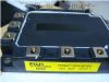
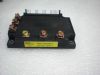
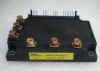
 7MBP75RJ120 Data Sheet