Features: • Up to 8000 Gate Array Gates (20,000 PLD equivalent gates)
• Replaces up to 200 TTL Packages
• Replaces up to eighty 20-Pin PAL® Packages
• Design Library with over 500 Macro Functions
• Single-Module Sequential Functions
• Wide-Input Combinatorial Functions
• Up to 1232 Programmable Logic Modules
• Up to 998 Flip-Flops
• Datapath Performance at 105 MHz
• 16-Bit Accumulator Performance to 39 MHz
• Two In-Circuit Diagnostic Probe Pins Support Speed Analysis to 50 MHz
• Two High-Speed, Low-Skew Clock Networks
• I/O Drive to 10 mA
• Nonvolatile, User Programmable
• Logic Fully Tested Prior to Shipment
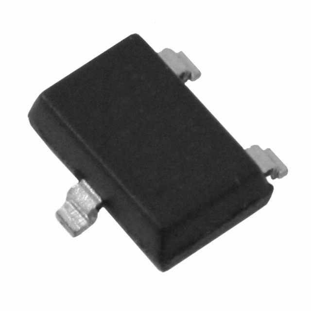
• 1.0-micron CMOS TechnologyPinout Specifications
| Symbol |
Parameter |
Limits |
Units |
| VCC |
DC Supply Voltage |
0.5 to +7.0 |
V |
| VI |
Input Voltage |
0.5 to VCC +0.5 |
V |
| VO |
Output Voltage |
0.5 to VCC +0.5 |
V |
| IIO |
I/O Source/Sink Current2 |
±20 |
mA |
| TSTG |
Storage Temperature |
65 to +150 |
|
Notes:
1. Stresses beyond those listed under "Absolute Maximum Ratings" may cause permanent damage to the device. Exposure to absolute maximum rated conditions for extended periods may affect device reliability. Device should not be operated outside the Recommended Operating Conditions.
2. Device inputs are normally high impedance and draw extremely low current. However, when input voltage is greater than VCC + 0.5 V or less than GND 0.5 V, the internal protection diode will be forward biased and can draw excessive
current.
DescriptionThe ACT™ 2 family represents Actel's second generation of field programmable gate arrays (FPGAs). The ACT 2 family presents a two-module architecture, consisting of C-modules and S- odules. These modules are optimized for both combinatorial and sequential designs. Based on Actel's patented channeled array architecture, the ACT 2 family provides significant enhancements to gate density and performance while maintaining downward compatibility with the ACT 1 design environment and upward compatibility with the ACT 3 design environment. The devices are implemented in silicon gate, 1.0-m, two-level metal CMOS, and employ Actel's PLICE® antifuse technology. This revolutionary architecture offers gate array design flexibility, high performance, and fast time-to-production with user programming. The ACT 2 family is supported by the Designer and Designer Advantage Systems, which offers automatic pin assignment, validation of electrical and design rules, automatic placement and routing, timing analysis, user programming, and diagnostic probe capabilities. The systems are supported on the following platforms: 386/486™ PC, Sun™, and HP™ workstations. The systems provide CAE interfaces to the following design environments: Cadence, Viewlogic®, Mentor Graphics®, and OrCAD™.

 A1225A Data Sheet