Series: -
Number of Outputs: 1
Evaluation Tools: -
Voltage - Supply: 3 V ~ 5.5 V
Packaging: Tube
Applications: PWM Motor Driver
Mounting Type: Through Hole
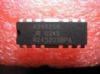
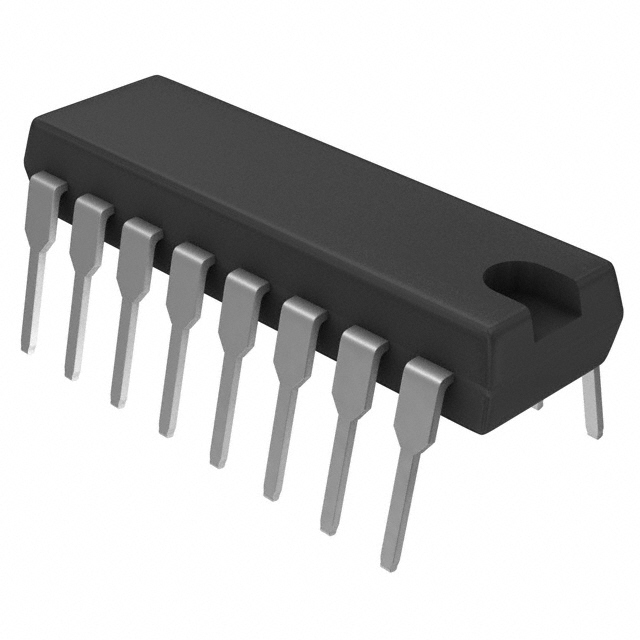
Package / Case: 16-DIP (0.300", 7.62mm)
Supplier Device Package: 16-DIP
Operating Temperature: -20°C ~ 85°C
Manufacturer: Allegro Microsystems Inc
Current - Output: ±1.3A
Voltage - Load: 3 V ~ 50 V
Features: ±1.3 A Continuous Output Current
50 V Output Voltage Rating
3 V to 5.5 V Logic Supply Voltage
Internal PWM Current Control
Saturated Sink Drivers (Below 1 A)
Fast and Slow Current-Decay Modes
Automotive Capable
Sleep (Low Current Consumption) Mode
Internal Transient- Suppression Diodes
Internal Thermal- Shutdown Circuitry
Crossover-Current and UVLO ProtectionPinout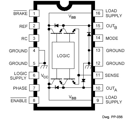 Specifications
Load Supply Voltage, VBB . . . . . .. . . . . 50 V
Output Current, IOUT
(Continuous) . . . . . . . . . . . . ........ . ±1.3 A*
Logic Supply Voltage, VCC . . . .. . . . . . 7.0 V
Logic/Reference Input Voltage Range,
VIN . . . . . . . . ......... . . -0.3 V to VCC + 0.3 V
Sense Voltage, VSENSE
(VCC = 5.0 V) . . . . . . . . . . . . . . ........ . 1.0 V
(VCC = 3.3 V) . . . . . . . . . . . ........ . . . . 0.4 V
Package Power Dissipation,
PD . . . . . . . . . . . . . . . . . ........ . . See Graph
Operating Temperature Range,
TA . . . . . . . . . . . . . . ...... . -20°C to +85°C
Junction Temperature, TJ . . . . . . . +150°C†
Storage Temperature Range,
TS . . . . . . . . . . . . . ...... . -55°C to +150°C
* Output current rating may be limited by duty cycle, ambient temperature, and heat sinking. Under any set of conditions, do not exceed the specified current rating or a junction temperature of 150°C.
† Fault conditions that produce excessive junction temperature will activate the device's thermal shutdown circuitry. These conditions can be tolerated but should be avoided.
DescriptionDesigned for bidirectional pulse-width modulated (PWM) current control of inductive loads, the A3953S- is capable of continuous output currents to ±1.3 A and operating voltages to 50 V. Internal fixed off-time PWM currentcontrol circuitry can be used to regulate the maximum load current to a desired value. The peak load current limit is set by the user's selection of an input reference voltage and external sensing resistor. The fixed off-time pulse duration is set by a user- selected external RC timing network. Internal circuit protection includes thermal shutdown with hysteresis, transient-suppression diodes, and crossover current protection. Special power-up sequencing is not required.
With the ENABLE input held low, the PHASE input controls load current polarity by selecting the appropriate source and sink driver pair. The MODE input determines whether the PWM current-control circuitry operates in a slow current-decay mode (only the selected source driver switching) or in a fast current-decay mode (selected source and sink switching). A user-selectable blanking window prevents false triggering of the PWM current-control circuitry. With the ENABLE input held high, all output drivers are disabled. A sleep mode is provided to reduce power consumption.
When a logic low is applied to the BRAKE input, the braking function is enabled. This overrides ENABLE and PHASE to turn off both source drivers and turn on both sink drivers. The brake function can be used to dynamically brake brush dc motors.
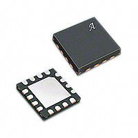
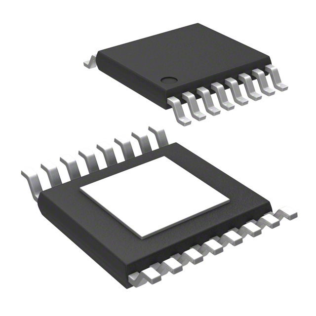
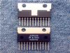
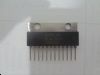
The A3953S- is supplied in a choice of two power packages; a 16-pin dual-in-line plastic package with copper heat-sink tabs, and a 16-pin plastic SOIC with copper heat-sink tabs. For both package styles, the power tab is at ground potential and needs no electrical isolation. Each package type is available in a lead-free version (100% matte tin plated leadframe).
Parameters: | Technical/Catalog Information | A3953SB |
| Vendor | Allegro Microsystems Inc |
| Category | Integrated Circuits (ICs) |
| Applications | PWM Motor Driver |
| Number of Outputs | 1 |
| Voltage - Supply | 3 V ~ 5.5 V |
| Voltage - Load | 3 V ~ 50 V |
| Current - Output | ±1.3A |
| Operating Temperature | -20°C ~ 85°C |
| Package / Case | 16-DIP |
| Packaging | Tube |
| Lead Free Status | Contains Lead |
| RoHS Status | RoHS Non-Compliant |
| Other Names | A3953SB
A3953SB
|
 A3953SB Data Sheet