Features: `High Integration:
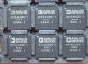
`32-Channel DAC in 12 mm* 12 mm CSPBGA
`Guaranteed Monotonic to 14 Bits
`Infinite Sample-and-Hold Capability to ±0.018% Accuracy
`Infinite Sample-and-Hold Total Unadjusted Error ±2.5 mV
`Adjustable Voltage Output Range
`Readback Capability
`DSP/Microcontroller Compatible Serial Interface
`Output Impedance 0.5
`Output Voltage Span 10 V
`Temperature Range 40 to +85Application·Automatic Test Equipment
·Optical Networks
·Level Setting
·Instrumentation
·Industrial Control Systems
·Data Acquisition
·Low Cost I/OPinout Specifications
VDD to AGND . . . . . . . . . . . . . . . . . . . . . . .... .. 0.3 V to +17 V
VSS to AGND . . . . . . . . . . . . . . . . . . . ..... . . .. . +0.3 V to 17 V
AVCC to AGND, DAC_GND . . . . . . . . . . ........... . . 0.3 V to +7 V
DVCC to DGND . . . . . . . . . . . . . . . . . . . . ........ . . 0.3 V to +7 V
Digital Inputs to DGND . . . . . . . ............ 0.3 V to DVCC + 0.3 V
Digital Outputs to DGND . . . . . . . . ........ 0.3 V to DVCC + 0.3 V
REF_IN to AGND, DAC_GND . . ............. . 0.3 V to AVCC + 0.3 V
VIN to AGND, DAC_GND . . . . . . ........... . 0.3 V to AVCC + 0.3 V
VOUT031 to AGND . . . . . . . .. ...... . VSS 0.3 V to VDD + 0.3 V
OFFS_IN to AGND . . . . . . . . ........... . VSS 0.3 V to VDD + 0.3 V
OFFS_OUT to AGND . . . ............... AGND 0.3 V to AVCC + 0.3 V
AGND to DGND . . . . . . . . . . . . . . . . . .. . .......... 0.3 V to +0.3 V
Operating Temperature Range
Industrial . . . . . . . . . . . . . . . . . . . . . . . . . ..... 40°C to +85°C
Storage Temperature Range . . . . . . . . . . . ..65°C to +150°C
Junction Temperature (TJ max) . . . . . . . . . . . . ..... . . . . . 150°C
74-Lead CSPBGA Package, JA Thermal Impedance .... 41°C/W
Reflow Soldering
Peak Temperature . . . . . . . . . . . . . . . . . . . . . . .. . . .......220°C
Time at Peak Temperature . . . . . . . . . . . . ......10 sec to 40 sec
Max Power Dissipation . . . . . . . . ....... (150°C TA)/JA mW3
Max Continuous Load Current at TJ = 70°C,
per Channel Group . . . . . . . . . . . . . . . . . ...... .. . . . . 15.5 mA4
NOTES
1 Stresses above those listed under Absolute Maximum Ratings may cause permanent damage to the device. This is a stress rating only; functional operation of the device at these or any other conditions above those listed in the operational sections of this specification is not implied. Exposure to absolute maximum rating conditions for extended periods may affect device reliability.
2 Transient currents of up to 100 mA will not cause SCR latch-up.
3 This limit includes load power.
4 This maximum allowed continuous load current is spread over eight channels, with channels grouped as follows:
Group 1: Channels 3, 4, 5, 6, 7, 8, 9, 10
Group 2: Channels 14, 16, 18, 20, 21, 24, 25, 26
Group 3: Channels 15, 17, 19, 22, 23, 27, 28, 29
Group 4: Channels 0, 1, 2, 11, 12, 13, 30, 31
| DAC Input Format |
Ser,SPI |
| # DAC Outputs |
32 |
| Pwr Diss |
623mW |
| DAC Uni or Bip |
Uni/Bip |
| DAC Vout Swing max |
14.5V p-p |
| Output FSR |
User Def. Range/Offset |
| Package |
BGA |
| Resolution (Bits) |
14bit |
| Supply Vnom |
Multi(±l2, +5An, +3Dig),Multi(±l2, +5An, +5Dig),Multi(±l5, +5An, +3Dig),Multi(±l5, +5An, +5Dig) |
DescriptionThe AD5532B is a 32-channel, voltage output, 14-bit DAC with an additional precision infinite sample-and-hold mode. The selected DAC register is written to via the 3-wire serial interface and VOUT for this DAC is then updated to reflect the new contents of the DAC register. DAC selection is accomplished via address bits A0A4. The output voltage range is determined by the offset voltage at the OFFS_IN pin and the gain of the output amplifier. It is restricted to a range from VSS + 2 V to VDD 2 V because of the headroom of the output amplifier.
The device AD5532B is operated with AVCC = +5 V ± 5%, DVCC = +2.7 V to +5.25 V, VSS = 4.75 V to 16.5 V, and VDD = +8 V to +16.5 V and requires a stable 3 V reference on REF_IN as well as an offset voltage on OFFS_IN.

 AD5532B Data Sheet