Features: ·60 MHz Pulse Rate·8-Bit Resolution·Center, Left or Right Justify·Low Power: 700 mW typical·Minimum Pulse Width: <5 ns·Maximum PW: 100 % Full-scaleApplication·Laser Printers·Digital Copiers·Color CopiersPinoutSpecificationsPositive Supply Voltage . . . . . . . . . . . . . . . . . . . ...
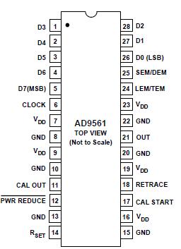
AD9561: Features: ·60 MHz Pulse Rate·8-Bit Resolution·Center, Left or Right Justify·Low Power: 700 mW typical·Minimum Pulse Width: <5 ns·Maximum PW: 100 % Full-scaleApplication·Laser Printers·Digital Cop...
SeekIC Buyer Protection PLUS - newly updated for 2013!
268 Transactions
All payment methods are secure and covered by SeekIC Buyer Protection PLUS.
Positive Supply Voltage . . . . . . . . . . . . . . . . . . . . . . . . +7 V
Digital Input Voltage Range . . . . . . . . . . . . . . 0.5 V to VDD
Minimum RSET . . . . . . . . . . . . . . . . . . . . . . . . . . . .. . . 120 W
Digital Output Current (Sourcing)2 . . . . . . . . . . . . . . . 10 mA
Digital Output Current (Sinking)2 . . . . . . . . . . . . . . . . 10 mA
Operating Temperature Range3 . . . . . . . . . . 0°C to +70°C
Storage Temperature Range . . . . . . . . . 65°C to +150°C
Junction Temperature . . . . . . . . . . . . . . . . . . . . . . .+150°C
Lead Soldering Temperature (10 sec)4 . . . . . . .. . . .+300°C
NOTES
1Absolute maximum ratings are limiting values, to be applied individually, and beyond which serviceability may be impaired. Functional operation under any of these conditions is not necessarily implied.
2CAL OUT should drive a single TTL or CMOS input.
3Typical Thermal Impedance: 28-lead SOIC (plastic) JA = 71.4 °C/W; JC = 23°C/W.
4When soldering surface mount packages in vapor phase equipment, temperature should not exceed 220°C for more than one minute.
The AD9561 is a second generation high speed, digitally programmable pulse width modulator (PWM). Output pulse width is proportional to an 8-bit DATA input value. Two additional control inputs determine if the pulse is placed at the beginning, middle or end of the clock period. Pulse width and placement can be changed every clock cycle up to 60 MHz.
Pulse width modulation is a well proven method for controlling gray scale and resolution enhancement in scanning laser print engines. Modulating pulse width provides the most cost effective method for continuous tone reproduction and resolution enhancement in low-to-moderate cost scanning electrophotographic systems.
The AD9561 uses precision analog circuits to control dot size so that near-photographic quality images are practical without the high frequency clock signals required by all digital approaches.
The AD9561 has improved features and performance over its predecessor, the AD9560. An improved ramp topology enables control of pulse width through 100% of the dot clock period as opposed to 95% for the AD9560. This enables smooth transition across dot boundaries for line screen applications.
Additionally, input data setup and hold time are symmetrical at 2 ns each, simplifying interface to the system bus.
Finally, chip design and pinout are optimized to decrease sensitivity of analog circuits to digital coupling. (See layout section for detailed recommendations for optimum results.)
Inputs are TTL or CMOS compatible, and outputs are CMOS compatible. The AD9561JR is packaged in a 28-lead plastic SOIC. It is rated over the commercial temperature range, 0°C to +70°C.