Features: 0.1 F to 10 mF Capacitors 120 kB/s Data Rate 2 Receivers Active in Shutdown (ADM213) On-Board DC-DC Converters ±9 V Output Swing with +5 V Supply Low Power (15 W) Low Power Shutdown £5 mW ±30 V Receiver Input Levels Latch-Up FREE Plug-In Upgrade for MAX205-211/213
ApplicationComputers Peripherals Modems Printers Instruments
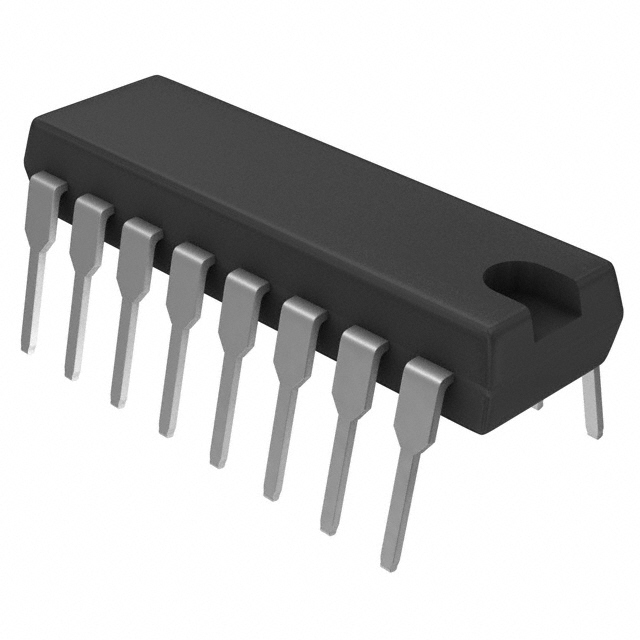
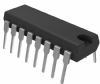
Pinout Specifications
(TA = +25°C unless otherwise noted)
VCC . . . . . . . . . . . . . . . . . . . . . . . . . . . . . . . . ..................... 0.3 V to +6 V
V+ . . . . . . . . . . . . . . . . . . . . . . . . . . . .................... (VCC 0.3 V) to +14 V
V . . . . . . . . . . . . . . . . . . . . . . . . . . . . . . . . . .................. +0.3 V to 14 V
Input Voltages
TIN . . . . . . . . . . . . . . . . . . . . . . . . . .......................0.3 V to (VCC + 0.3 V)
RIN . . . . . . . . . . . . . . . . . . . . . . . . . . . . . . . . . . . . . . ........................±30 V
Output Voltages
TOUT . . . . . . . . . . . . . . . . . . ......................... (V+, + 0.3 V) to (V, 0.3 V)
ROUT . . . . . . . . . . . . . . . . . . . . . . . ....................... 0.3 V to (VCC + 0.3 V)
Short Circuit Duration
TOUT . . . . . . . . . . . . . . . . . . . . . . . . . . . . . . . . ......................... Continuous
Power Dissipation
N-24 DIP (Derate 13.5 mW/°C above +70°C) . . ........................1000 mW
N-24A DIP (Derate 13.5 mW/°C above +70°C) . . ........................500 mW
R-24 SOIC (Derate 12 mW/°C above +70°C) . . . . .......................850 mW
R-28 SOIC (Derate 12.5 mW/°C above +70°C) . ......................... 900 mW
RS-28 SSOP (Derate 10 mW/°C above +70°C) . . . .......................900 mW
Q-24 Cerdip (Derate 12.5 mW/°C above +70°C) ........................1000 mW
D-24 Ceramic (Derate 20 mW/°C above +70°C) . .......................1000 mW
Thermal Impedance, qJA
N-24 DIP . . . . . . . . . . . . . . . . . . . . . . . . . . . . . . . . ........................120°C/W
N-24A DIP . . . . . . . . . . . . . . . . . . . . . . . . . . . . . ........................... 110°C/W
R-24 SOIC . . . . . . . . . . . . . . . . . . . . . . . . . . . . . . . ......................... 85°C/W
R-28 SOIC . . . . . . . . . . . . . . . . . . . . . . . . . . . . . . . ......................... 80°C/W
RS-28 SSOP . . . . . . . . . . . . . . . . . . . . . . . . . . . . . ..........................100°C/W
Q-14 Cerdip . . . . . . . . . . . . . . . . . . . . . . . . . . . . . ......................... 105°C/W
Q-16 Cerdip . . . . . . . . . . . . . . . . . . . . . . . . . . . . ......................... . 100°C/W
Q-20 Cerdip . . . . . . . . . . . . . . . . . . . . . . . . . . . . . . ........................100°C/W
Q-24 Cerdip . . . . . . . . . . . . . . . . . . . . . . . . . . . . . . . ........................55°C/W
D-24 Ceramic . . . . . . . . . . . . . . . . . . . . . . . . . . . . ........................... 50°C/W
Operating Temperature Range
Industrial (A Version) . . . . . . . . . . . . . . . . . ........................-40°C to +85°C
Storage Temperature Range . . . . . . . . . . . . ...................65°C to +150°C
Lead Temperature, Soldering . . . . . . . . . . . . . . . . . . ....................... +300°C
Vapour Phase (60 sec) . . . . . . . . . . . . . . . . . . . . . . ......................... +215°C
Infrared (15 sec) . . . . . . . . . . . . . . . . . . . . . . . . . . . ........................ +220°C
ESD Rating . . . . . . . . . . . . . . . . . . . . . . . . . . . . . . . . ........................> 2000 V
*This is a stress rating only and functional operation of the device at these or any other conditions above those indicated in the operation sections of this specification is not implied. Exposure to absolute maximum rating conditions for extended periods of time may affect reliability.
| Protocols |
RS-232 |
| Pwr Supply (Vnom) |
+5 |
| #Tx |
4 |
| # Rx |
5 |
| Data Rate |
120kbps |
| Low Power Shutdown |
Y |
| Operating Temp Range |
-40 to +85 |
DescriptionThe ADM2xx family of line drivers/receivers is intended for all EIA-232-E and V.28 communications interfaces, especially in applications where ±12 V is not available. The ADM2xx feature a low power shutdown mode which reduces power dissipation to less than 5 mW making ADM2xx ideally suited for battery powered equipment. The ADM205 does not require any external components and is particularly ,useful in applications where printed circuit board space is critical. The ADM213 has an active-low shutdown and an active-high receiver enable control. Two receivers of the ADM213 remain active during shutdown. This feature is useful for ring indicator monitoring.
All members of the ADM2xx family, except the ADM209, include two internal charge pump voltage converters which allow operation from a single +5 V supply. These converters convert the +5 V input power to the ±10 V required for RS-232 output levels. The ADM209 is designed to operate from +5 V and +12 V supplies. An internal +12 V to 12 V charge pump voltage converter generates the 12 V supply.

 ADM211 Data Sheet