AM26LV32E

Features: ` Meets or Exceeds Standard TIA/EIA-422-B and ITU Recommendation V.11` Operates From a Single 3.3-V Power Supply` ESD Protection for RS422 Bus Pins ±15-kV Human-Body Model (HBM) ±8-kV IEC61000-4-2, Contact Discharge ±15-kV IEC61000-4-2, Air-Gap Discharge` Switching Rates up to 32 MHz` Lo...

product image

AM26LV32E Picture
SeekIC No. : 004282099 Detail

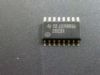
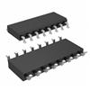
AM26LV32E: Features: ` Meets or Exceeds Standard TIA/EIA-422-B and ITU Recommendation V.11` Operates From a Single 3.3-V Power Supply` ESD Protection for RS422 Bus Pins ±15-kV Human-Body Model (HBM) ±8-kV IEC6...

floor Price/Ceiling Price

Part Number:
AM26LV32E
Supply Ability:
5000

Price Break

  • Qty
  • 1~5000
  • Unit Price
  • Negotiable
  • Processing time
  • 15 Days
Total Cost: $ 0.00

SeekIC Buyer Protection PLUS - newly updated for 2013!

  • Escrow Protection.
  • Guaranteed refunds.
  • Secure payments.
  • Learn more >>

Month Sales

268 Transactions

Rating

evaluate  (4.8 stars)

Upload time: 2025/12/5

Payment Methods

All payment methods are secure and covered by SeekIC Buyer Protection PLUS.

Notice: When you place an order, your payment is made to SeekIC and not to your seller. SeekIC only pays the seller after confirming you have received your order. We will also never share your payment details with your seller.
Product Details

Description


Features:

` Meets or Exceeds Standard TIA/EIA-422-B and ITU Recommendation V.11
` Operates From a Single 3.3-V Power Supply
` ESD Protection for RS422 Bus Pins
±15-kV Human-Body Model (HBM)
±8-kV IEC61000-4-2, Contact Discharge
±15-kV IEC61000-4-2, Air-Gap Discharge
` Switching Rates up to 32 MHz
` Low Power Dissipation: 27 mW Typ
` Open-Circuit, Short-Circuit, and Terminated Fail-Safe
` ±7-V Common-Mode Input Voltage Range With ±200-mV Sensitivity
` Accepts 5-V Logic Inputs With 3.3-V Supply (Enable Inputs)
` Input Hysteresis: 35 mV Typ
` Pin-to-Pin Compatible With AM26C32, AM26LS32
` Ioff Supports Partial-Power-Down Mode Operation
` Package Options: SOP, SOIC, TSSOP, QFN


Pinout

  Connection Diagram


Specifications

  MIN                      MAX UNIT
VCC                Supply voltage range(3) 0.5                      6 V
 VI                  Input voltage range A or B inputs 14                      14 V
Enable Inputs 0.5                       6 V
VID                 Differential input voltage(4) 14                       14 V
VO                  Output voltage range 0.5                        6 V
IIK                  Input clamp current range VI < 0                              20 mA
IOK                 Output clamp current range VO < 0                              20 mA
l                   Maximum output current                              ±20 mA
TJ                    Operating virtual junction temperature                               150
JA               Package thermal impedance(5) (6) D package                                 73 /W
NS package                                 64
PW package                               108
RGY package                                 39
T               Operating free-air temperature range 40                         85
Tstg             Storage temperature range 65                       150

(1) Stresses beyond those listed under "absolute maximum ratings" may cause permanent damage to the device. These are stress ratings only, and functional operation of the device at these or any other conditions beyond those indicated under "recommended operating conditions" is not implied. Exposure to absolute-maximum-rated conditions for extended periods may affect device  reliability.
(2) This device is designed to meet TIA/EIA-422-B and ITU.
(3) All voltage values except differential input voltage are with respect to the network GND.
(4) Differential input voltage is measured at the noninverting input with respect to the corresponding inverting input.
(5) Maximum power dissipation is a function of TJ(max), JA, and TA. The maximum allowable power dissipation at any allowable ambient temperature is PD = (TJ(max) TA)/JA. Selecting the maximum of 150 can affect reliability.
(6) The package thermal impedance is calculated in accordance with JESD 51-7.


Description

The AM26LV32E consists of quadruple differential line receivers with 3-state outputs. These differential receivers have ±15-kV ESD (HBM and IEC61000-4-2, Air-Gap Discharge) and ±8-kV ESD (IEC61000-4-2, Contact Discharge) protection for RS422 bus pins.

This device is designed to meet TIA/EIA-422-B and ITU recommendation V.11 drivers with reduced supply voltage. The device is optimized for balanced bus transmission at switching rates up to 32 MHz. The 3-state outputs permit connection directly to a bus-organized system.

The AM26LV32E has an internal fail-safe circuitry that prevents the device from putting an unknown voltage signal at the receiver outputs. In the open fail-safe, shorted fail-safe, and terminated fail-safe, a high state is produced at the respective output.

This device is supported for partial-power-down applications using Ioff. Ioff circuitry disables the outputs, preventing damaging current backflow through the device when it is powered down.

The AM26LV32EI is characterized for operation from 40 to 85.


Customers Who Bought This Item Also Bought

Margin,quality,low-cost products with low minimum orders. Secure your online payments with SeekIC Buyer Protection.
Programmers, Development Systems
Power Supplies - External/Internal (Off-Board)
Sensors, Transducers
Potentiometers, Variable Resistors
Isolators
Cables, Wires
View more