Maximum Operating Temperature
: + 85 C
Mounting Style
: SMD/SMT
Memory Size
: 512 Kbit
Organization
: 64 K x 8
Maximum Operating Current
: 3 mA
Operating Supply Voltage
: 3.3 V, 5 V
Maximum Clock Frequency
: 1 MHz
Data Retention
: 40 Years
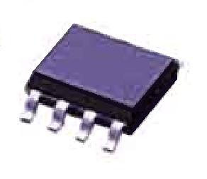
Package / Case
: SOIC EIAJ
Pinout Description
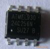
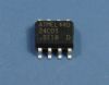
The AT24C512BN-SH25-T is one member of the AT24C512B series.It has the following features including (1)schmitt trigger, filtered inputs for noise suppression;(2)write protect pin for hardware and software data protection;(3)128-byte page write mode (partial page writes allowed);(4)die sales: wafer form, waffle pack and bumped die.
The AT24C512B provides 524,288 bits of serial electrically erasable and programmable read only memory (EEPROM) organized as 65,536 words of 8 bits each. The device's cascadable feature allows up to eight devices to share a common two-wire bus. The device is optimized for use in many industrial and commercial applications where low-power and low-voltage operation are essential. The devices are available in space-saving 8-pin PDIP, 8-lead JEDEC SOIC, 8-lead EIAJ SOIC, 8-lead TSSOP, 8-ball dBGA2 and 8-lead Ultra Thin SAP packages. In addition, the entire family is available in 1.8V (1.8V to 3.6V) and 2.5V (2.5V to 5.5V) versions.Stresses beyond those listed under "Absolute Maximum Ratings" may cause permanent damage to the device. This is a stress rating only and functional operation of the device at these or any other conditions beyond those indicated in the operational sections of this specification is not implied. Exposure to absolute maximum rating conditions for extended periods may affect device reliability.
Sequential reads are initiated by either a current address read or a random address read. After the microcontroller receives a data word,AT24C512BN-SH25-T responds with an acknowledge. As long as the EEPROM receives an acknowledge, it will continue to increment the data word address and serially clock out sequential data words. When the memory address limit is reached, the data word address will roll over and the sequential read will continue.A page write is initiated the same way as a byte write, but the microcontroller does not send a stop condition after the first data word is clocked in. Instead, after the EEPROM acknowledges receipt of the first data word, the microcontroller can transmit up to 127 more data words. The EEPROM will respond with a "0" after each data word received. The microcontroller AT24C512BN-SH25-T must terminate the page write sequence with a stop condition.
Parameters: | Technical/Catalog Information | AT24C512BN-SH25-T |
| Vendor | Atmel (VA) |
| Category | Integrated Circuits (ICs) |
| Memory Type | EEPROM |
| Memory Size | 512K (64K x 8) |
| Speed | 1MHz |
| Interface | I²C, 2-Wire Serial |
| Package / Case | 8-SOIC |
| Packaging | Digi-Reel? |
| Voltage - Supply | 2.5 V ~ 5.5 V |
| Operating Temperature | -40°C ~ 85°C |
| Format - Memory | EEPROM - Serial |
| Lead Free Status | Lead Free |
| RoHS Status | RoHS Compliant |
| Other Names | AT24C512BN SH25 T
AT24C512BNSH25T
AT24C512BN SH25 TDKR ND
AT24C512BNSH25TDKRND
AT24C512BN-SH25-TDKR
|
 AT24C512BN-SH25-T Data Sheet