Features: Driver Features
Produces a logic zero in third state
400 mV difference voltage in third state
Two line drivers per package
Logic to convert TTL input logic levels to differential, pseudo-emmiter coupled logic (ECL) output logic levels
No line loading when VCC = 0 V
High output driver for 50 loads
200 mA short-circuit current (typical)
2.0 ns maximum propagation delay
<0.2 ns output skew (typical)
Receiver Features
Two line receivers per package
High input impedance 8 k
Logic that converts differential input logic levels to TTL output logic levels
4.0 ns maximum propagation delay
<0.20 V input sensitivity (typical)
-1.2 V to , 7.2 V common-mode range
Common Device Features
Common enable for each driver/receiver pair
Operating temperature range: 40 to +125 (wider than the 41 Series)
Single 5.0 V ± 5% supply
400 Mbits/s maximum data rate
Meets enhanced small device interface (ESDI)
Electrostatic discharge (ESD) performance better than the 41 Series
Lower power requirement than the 41 SeriesPinout SpecificationsStresses in excess of the absolute maximum ratings can cause permanent damage to the device. These are absolute stress ratings only. Functional operation of the device is not implied at these or any other conditions in excess of those given in the operational sections of the data sheet. Exposure to absolute maximum ratings for extended periods can adversely affect device reliability.
| Parameter |
Symbol |
Min |
Max |
Unit |
| Power Supply Voltage |
VCC |
- |
6.5 |
V |
| Ambient Operating Temperature |
TA |
-40 |
125 |
|
| Storage Temperature |
Tstg |
-55 |
150 |
|
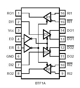
DescriptionThe BTF1A device is a dual differential transceiver circuit that transmits and receives digital data over balanced transmission lines and is compatible with Lucent Technologies Microelectronics Group differential drivers and receivers. BTF1A is designed to provide a strong logic zero when in the third state. The minimum difference voltage in the third state is 400 mV. BTF1A is designed specifically for bus applications where a well-defined logic state is needed when the bus is idle. The driver puts out a logic
zero when in the third state mode, which is easily overriden by an active buffer on the bus. When all the buffers on the bus are inactive (third state), the signal on the bus is a
zero indicating that the bus is idle.
The dual drivers BTF1A translate input TTL logic levels to differential pseudo-ECL output levels. The dual receiver BTF1A converts differential input logic levels to TTL output levels. Each driver/receiver pair has its own common enable control allowing serial data and a control clock to be transmitted and received on a single integrated circuit. The BTF1A transceiver requires the customer to supply termination resistors on the circuit board.
The powerdown loading characteristics of the receiver BTF1A input circuit are approximately 8 k relative to the power supplies; hence, it will not load the transmission line when the circuit is powered down. For those circuits with termination resistors, the line will remain impedance matched when the circuit is powered down. The driver BTF1A does not load the line when it is powered down.

 BTF1A Data Sheet


