Features: ` Wide power-supply voltage range: 2 to 36 V
` Very low supply current: 0.8 mA
` Low input bias current: 25 nA
` Low input offset current: 5 nA
` Low input offset voltage: 2 mV
` The common-mode input voltage range includes ground.
` Low output saturation voltage: 1 mV (5 A), 70 mV (1 mA)
` Output voltages compatible with CMOS logic systemsApplication` Square-Wave Oscillator
The circuit shown in figure one has the same structure as a single-voltage power supply astable multivibrator. Figure 2 shows the waveforms generated by this circuit.
` Pulse Generator
The charge and discharge circuits in the circuit from figure 1 are separated by diodes in this circuit. (See figure 3.) This allows the pulse width and the duty cycle to be set independently. Figure 4 shows the waveforms generated by this circuit.
` Voltage Controlled Oscillator
In the circuit in figure 5, comparator A1 operates as an integrator, A2 operates as a comparator with hysteresis, and A3 operates as the switch that controls the oscillator frequency. If the output Vout1 is at the low level, the A3 output will go to the low level and the A1 inverting input will become a lower level than the A1 noninverting input. The A1 output will integrate this state and its output will increase towards the high level. When the output of the integrator A1 exceeds the level on the comparator A2 inverting input, A2 inverts to the high level and both the output Vout1 and the A3 output go to the high level. This causes the integrator to integrate a negative state, resulting in its output decreasing towards the low level. Then, when the A1 output level becomes lower than the level on the A2 noninverting input, the output Vout1 is once again inverted to the low level. This operation generates a square wave
on Vout1 and a triangular wave on Vout2.
` Basic Comparator
The circuit shown in figure 6 is a basic comparator. When the input voltage VIN exceeds the reference voltage VREF, the output goes to the high level.
` Noninverting Comparator (with Hysteresis)
Assuming +VIN is 0V, when VREF is applied to the inverting input, the output will go to the low level (approximately 0V). If the voltage applied to +VIN is gradually increased, the output will go high when the value of the noninverting input, +VIN *R2/(R1 + R2), exceeds +VREF. Next, if +VIN is gradually lowered, Vout will be inverted to the low level once again when the value of the noninverting input, (Vout VIN)*R1/(R1 + R2), becomes lower than VREF. With the circuit constants shown in figure 7, assuming VCC = 15V and +VREF = 6V, the following formula can be derived, i.e. +VIN*10M/(5.1M + 10M) > 6V, and Vout will invert from low to high when +VIN is > 9.06V.
(Vout-VIN)*R1/(R1+R2)+VIN<6V
(Assuming Vout = 15V)
When +VIN is lowered, the output will invert from high to low when +VIN < 1.41V. Therefore this circuit has a hysteresis of 7.65V. Figure 8 shows the input characteristics
`Inverting Comparator (with Hysteresis)
In this circuit, the output Vout inverts from high to low when +VIN > (VCC + Vout)/3. Similarly, the output Vout inverts from low to high when +VIN < VCC/3. With the circuit constants shown in figure 9, assuming VCC = 15V and Vout = 15V, this circuit will have a 5V hysteresis. Figure 10 shows the I/O characteristics for the circuit in figure 9
` Zero-Cross Detector (Single-Voltage Power Supply)
In this circuit, the noninverting input will essentially beheld at the potential determined by dividing VCC with 100k and 10k resistors. When VIN is 0V or higher, the output will be low, and when VIN is negative, Vout will invert to the high level. (See figure 11.)
DescriptionThe HA17339(A) series products are comparators designed for general purpose, especially for power control systems.
These HA17339(A) series ICs operate from a single power-supply voltage over a wide range of voltages, and feature a reduced power-supply current since the supply current is independent of the supply voltage.
These HA17339(A) series comparators have the merit which ground is included in the common-mode input voltage range at a single-voltage power supply operation. These products have a wide range of applications, including limit comparators, simple A/D converters, pulse/square-wave/time delay generators, wide range VCO circuits, MOS clock timers, multivibrators, and high-voltage logic gates.

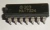
 HA17339A Data Sheet