| Item |
Features |
| LSI |
• Operating frequency: 200 MHz
• Performance: 360MIPS, 1.4 GFLOPS
• Voltage: 1.5 V (internal), 3.3 V (I/O)
• Superscalar architecture: Parallel execution of two instructions
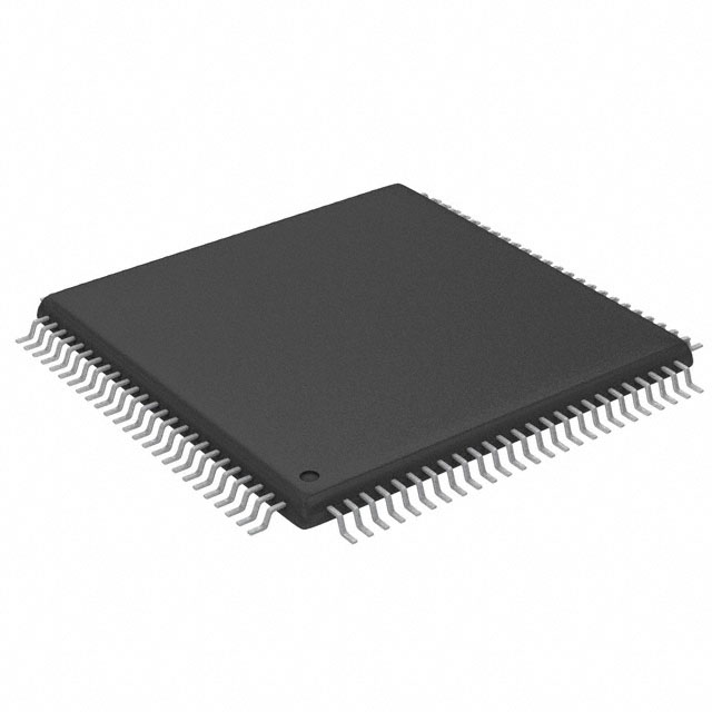
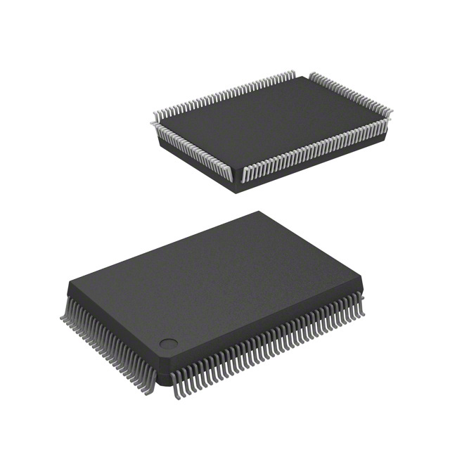
• Packages: 256-pin BGA (Size: 21 * 21 mm, pin pitch: 1.0 mm)
• External buses:
Separate 26-bit address and 32-bit data buses
External bus frequency: 67MHz
• Choice of MFI mode or LCD mode:
MFI mode: 8-/16-bit parallel interface
(supports 68-/80-family interface)
LCD mode: LCD controller/data output |
| CPU |
• Original Hitachi SuperH architecture
• 32-bit internal data bus
• General register file:
Sixteen 32-bit general registers (and eight 32-bit shadow registers)
Seven 32-bit control registers
Four 32-bit system registers
• RISC-type instruction set (upward-compatible with SuperH Series)
Fixed 16-bit instruction length for improved code efficiency
Load-store architecture
Delayed branch instructions
Conditional execution
C-based instruction set
• Superscalar architecture (providing simultaneous execution of two
instructions) including FPU
• Instruction execution time: Maximum 2 instructions/cycle
• Virtual address space: 4 Gbytes (448-Mbyte external memory space)
• Space identifier ASIDs: 8 bits, 256 virtual address spaces
• On-chip multiplier
• 5-stage pipeline |
| FPU |
• On-chip floating-point coprocessor
• Supports single-precision (32 bits) and double-precision (64 bits)
• Supports IEEE754-compliant data types and exceptions
• Two rounding modes: Round to Nearest and Round to Zero
• Handling of denormalized numbers: Truncation to zero or interrupt
generation for compliance with IEEE754
• Floating-point registers: 32 bits * 16 words * 2 banks
• 32-bit CPU-FPU floating-point communication register (FPUL)
• Supports FMAC (multiply-and-accumulate) instruction
• Supports FDIV (divide) and FSQRT (square root) instructions
• Supports FLDI0/FLDI1 (load constant 0/1) instructions
• Instruction execution times:
Latency (FMAC/FADD/FSUB/FMUL): 3 cycles (single-precision), 8
cycles (double-precision)
Pitch (FMAC/FADD/FSUB/FMUL): 1 cycle (single-precision), 6 cycles
(double-precision)
Note: FMAC is supported for single-precision only.
• 3-D graphics instructions (single-precision only):
4-dimensional vector conversion and matrix operations (FTRV): 4
cycles (pitch), 7 cycles (latency)
4-dimensional vector inner product (FIPR): 1 cycle (pitch), 4 cycles
(latency)
• 5-stage pipeline |
Clock pulse
generator (CPG) |
• Choice of main clock: 1, 6, or 12 times EXTAL
• Clock modes:
CPU frequency: 1, 1/2, 1/3, 1/4, 1/6, or 1/8 times main clock
Bus frequency: 1, 1/2, 1/3, 1/4, 1/6, or 1/8 times main clock
Peripheral frequency: 1/2, 1/3, 1/4, 1/6, or 1/8 times main clock
• Power-down modes:
Sleep mode
Deep sleep mode
Standby mode
Hardware standby mode
Module standby mode
• Single-channel watchdog timer |
Memory
management
unit (MMU) |
• 4-Gbyte address space, 256 address space identifiers (8-bit ASIDs)
• Single virtual mode and multiple virtual memory mode
• Supports multiple page sizes: 1 kbyte, 4 kbytes, 64 kbytes, 1 Mbyte
• 4-entry fully-associative TLB for instructions
• 64-entry fully-associative TLB for instructions and operands
• Supports software-controlled replacement and random-counter
replacement algorithm
• TLB contents can be accessed directly by address mapping |
| Cache memory |
• Instruction cache (IC)
16-kbyte, 2-way set associative (LRU)
256 entries, 32-byte block length
Cache-double-mode (16-kbyte cache)
Index mode
• Operand cache (OC)
32-kbyte, 2-way set associative (LRU)
512 entries, 32-byte block length
Cache-double-mode (32-kbyte cache)
Index mode
RAM mode (16-kbyte cache + 16-kbyte RAM)
Choice of write method (copy-back or write-through)
• Single-stage copy-back buffer, single-stage write-through buffer
• Cache memory contents can be accessed directly by address mapping
(usable as on-chip memory)
• Store queue (32 bytes * 2 entries) |
Interrupt controller
(INTC) |
• Nine independent external interrupts: NMI, IRL3 to IRL0, and IRQ7 to
IRQ4
• 15-level signed external interrupts: IRL3 to IRL0
• On-chip peripheral module interrupts: Priority level can be set for each
module |
User break
controller (UBC) |
• Supports debugging by means of user break interrupts
• Two break channels
• Address, data value, access type, and data size can all be set as break
conditions
• Supports sequential break function |
Bus state
controller (BSC) |
• Supports external memory access
• External memory space divided into seven areas, each of up to 64
Mbytes, with the following parameters settable for each area:
Bus size (8, 16, or 32 bits)
Number of wait cycles (hardware wait function also supported)
SRAM, synchronous DRAM, or burst ROM
Supports PCMCIA interface (only in little endian mode)
• Synchronous DRAM refresh functions:
Programmable refresh interval
Supports auto refresh mode and self-refresh mode
• Synchronous DRAM burst access function
• Big endian or little endian mode can be set |
Direct memory
access controller
(DMAC) |
• 8-channel physical address DMA controller
• Transfer data size: 8, 16, 32, or 64 bits, or 32 bytes
• Address modes:
1-bus-cycle single address mode
2-bus-cycle dual address mode
• Transfer requests: External, peripheral module, or auto-requests
• Choice of DACK or DRAK (four external pins)
• Bus modes: Cycle-steal or burst mode
• Supports on-chip FIFO bridge (16-stage * 32-bit FIFO * 7) to achieve
high-speed transfer for HAC/SSI, USB and LCDC |
| Timer unit (TMU) |
• 3-channel auto-reload 32-bit timer
• Input-capture function (only channel 2)
• Choice of six types counter input clocks (external and peripheral clocks) |
Compare match
timer (CMT) |
• 4-channel auto-reload 32-bit timers
• Choice of 16 or 32 bits
• Choice of 1-shot or free-running operation
• Choice of an interrupt source or DMA transfer request from compare
match or overflow |
Serial
communication
interface
(SCIF) |
• Three full-duplex communications channels
• On-chip 128-byte FIFOs for all channels
• Choice of asynchronous mode or synchronous mode
• Can select any bit rate generated by on-chip baud-rate generator
• On-chip modem control function (SCIF_RTS and SCIF_CTS) for channel
1 and 2 |
Hitachi audio codec
interface (HAC) |
• Digital interface for audio codec
• Supports transfer for slot 1 to slot 4
• Choice of 16- or 20-bit DMA transfer
• Supports various sampling rates by adjusting slot data
• Generates interrupt: data ready, data request, overflow, and underrun |
Serial sound
interface (SSI) |
• 2-channel bi-directional transfer (maximum)
• Support multi-channel and compressed-data transfer
• Selectable frame size |
I2C bus interface
(I2C) |
• 2 channels (maximum)
• Master/slave
• 16-byte FIFO
• Supports high-speed mode (400 kbits/sec)
• Supports version 1.0 |
Multimedia card
interface (MMCIF) |
• Supports MMC mode
• A maximum bit rate of 20 Mbps at 20 MHz of peripheral clock
• Interface with MCCLK output for transfer clock output, MCCMD I/O for
command output/response input, MCDAT I/O (data I/O)
• Four interrupt sources |
Smart card interface
(SIM) |
• Supports ISO/IEC7816-3 (Identification card)
• Asynchronous half-duplex transfer (8 bits)
• Can select any bit rate generated by on-chip baud-rate generator
• Generates and checks parity bit
• Four interrupt sources |
Hitachi controller
area network 2
(HCAN2) |
• 2 channels (maximum)
• Supports CAN specification 2.0A and 2.0B
Standard data and remote frame (11-bit ID)
Extended data and remote frame (29-bit ID)
• 32 independent message buffers using standard (11-bit) and extended
(29-bit) ID format
• 31 Mailboxes can be used for transmission or reception
• One Mailbox can be used for only reception
• Message reception filtering by IDs:
Standard message ID
Extended message ID
• Local reception filter for reception-only Mailbox (standard and extended
message ID) can be specified
• Power-down sleep mode
• A maximum of 1-Mbit/s CAN data transfer rate can be specified
• Transmit message queue having internal priority sorting mechanism which
handle priority-inversion issue of real time applications
• Data buffer access without hand-shaking |
Serial peripheral
interface (HSPI) |
• 1 channel
• Master/slave mode
• Selectable bit rate generated by on-chip baud-rate generator |
Multifunctional
interface (MFI) |
• 2-kbyte internal memory can be read from or written to via the MFI pin in
32-bit units or by the CPU in 8-/16-/32-bit units.
• Choice of 8- or 16-bit parallel interface
• Supports 68-/80-family interface (can be switched during reset)
• Endians can be switched |
| USB host |
• 1 channel
• Supports USB version 1.1 and OHCI 1.0
• Supports data transfer rate of 1.5 Mbps and 12Mbps
• On-chip 8-kbyte SRAM as shared memory defined in OHCI specification |
LCD controller
(LCDC) |
• Supports 16 * 1 to 1024 * 1024 dots (8 bpp: a maximum of 640 *480
dots, 16 bpp: a maximum of 400 * 240 dots)
• Supports 4, 8, 15, and 16 bpp color modes
• Supports 1, 2, 4, and 6 bpp grayscale modes.
• Supports TFT/DSTN/STN display
• Selectable signal polarities
• 24-bit color palette memory (16 bits of 24 bits are valid: R: 5/G: 6/B: 5)
• Unified graphics memory architecture |
| A/D converter (ADC) |
• 10-bit resolution
• 4-channel input
• Three types of conversion modes
Single mode: 1-channel A/D conversion
Multi mode: 1- to 4-channel A/D conversion
Scan mode: 1- to 4-channel A/D conversion
• Conversion time: 8 s for are channel (maximum)
• Absolute error ± 4LSB |
| General I/O (GPIO) |
• 70 general I/O port (69 for I/O and one for output) |

 HD6417760BP200D Data Sheet