Features: ·HVCMOS technology for high performance·High density integration ultrasound transmitter·0 to ±65V output voltage·±750mA source and sink current in Pulse mode·±110mA source and sink current in CW mode·Up to 20MHz operating frequency·Matched delay times·1.2V to 5.0V CMOS logic interface·Bu...
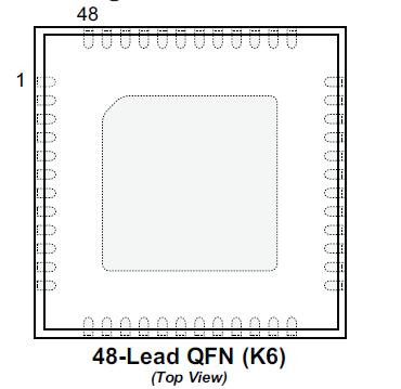
HV738: Features: ·HVCMOS technology for high performance·High density integration ultrasound transmitter·0 to ±65V output voltage·±750mA source and sink current in Pulse mode·±110mA source and sink current...
SeekIC Buyer Protection PLUS - newly updated for 2013!
268 Transactions
All payment methods are secure and covered by SeekIC Buyer Protection PLUS.
Parameter | Value |
VSS, Power supply reference VLL, Positive logic supply VDD, Positive logic and level translator supply (VPP -VPF) Positive fl oating gate drive supply (VNF- VNN) Negative gate fl oating drive supply (VPP-VNN) Differential high voltage supply VPP, High voltage positive supply VNN, High voltage negative supply OTP, Over Temperature Protection output All logic input PINX, NINX and EN voltages (VSUB - VSS) Substrate to VSS voltage difference (VPP TXPX) VPP to TXPX voltage difference (VSUB- TXPX) Substrate to TXPX voltage difference (TXNX-VNN ) TXNX to VNN voltage difference Operating temperature Storage temperature Thermal resistance, JA Thermal resistance, JC (Junction to thermal pad) |
0V -0.5V to +7V -0.5V to +14V -0.5V to +14V -0.5V to +14V +140V -0.5V to +70V +0.5V to 70V -0.5V to +7V -0.5V to +7V +140V +140V +140V +140V -40°C to 125° -65°C to 150° 29°C/W 0.5°C/W |
Absolute Maximum Ratings are those values beyond which damage to the device may occur. Functional operation under these conditions is not implied. Continuous operation of the device at the absolute rating level may affect device reliability. All voltages are referenced to device ground.
The Supertex HV738 is a four-channel, monolithic, high voltage, high speed pulse generator. It is designed for portable medical ultrasound applications. This high voltage and high speed integrated circuit can also be used for piezoelectric, capacitive or MEMS sensing in ultrasonic nondestructive detection and sonar ranger applications.
The HV738 consists of a controller logic interface circuit, level translators, MOSFET gate drivers and high current power P-channel and N-channel MOSFETs as the output stage for each channel.
The output stages of each channel are designed to provide peak output currents over ±1.1A for pulsing, when in mode 4, with up to ±65 volt swings. When in mode 1, all the output stages drop the peak current to ±140mA for low-voltage CW mode operation to decrease the power consumption of the HV738. The P and N type of power FETs gate drivers are supplied by two fl oating 8.0VDC power supplies referenced to VPP and VNN. This direct coupling topology of the gate drivers not only eliminates two high voltage capacitors per channel, but also makes the PCB layout easier.