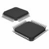
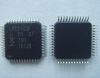
Features: · 16/32-bit ARM7TDMI-S microcontroller in a tiny LQFP64 package.
· 16 kB on-chip Static RAM.
· 128/256 kB on-chip Flash Program Memory. 128-bit wide interface/accelerator enables high speed 60 MHz operation.
· In-System Programming (ISP) and In-Application Programming (IAP) via on-chip boot-loader software. Flash programming takes 1 ms per 512 byte line. Single sector or full chip erase takes 400 ms.
· EmbeddedICE-RT interface enables breakpoints and watch points. Interrupt service routines can continue to execute whilst the foreground task is debugged with the on-chip RealMonitor software.
· Embedded Trace Macrocell enables non-intrusive high speed real-time tracing of instruction execution.
· Four channel 10-bit A/D converter with conversion time as low as 2.44 ms.
· Two 32-bit timers (with 4 capture and 4 compare channels), PWM unit (6 outputs),Real Time Clock and Watchdog.
· Multiple serial interfaces including two UARTs (16C550), Fast I2C (400 kbits/s) and two SPIs™.
· 60 MHz maximum CPU clock available from programmable on-chip Phase-Locked Loop.
· Vectored Interrupt Controller with configurable priorities and vector addresses.
Pinout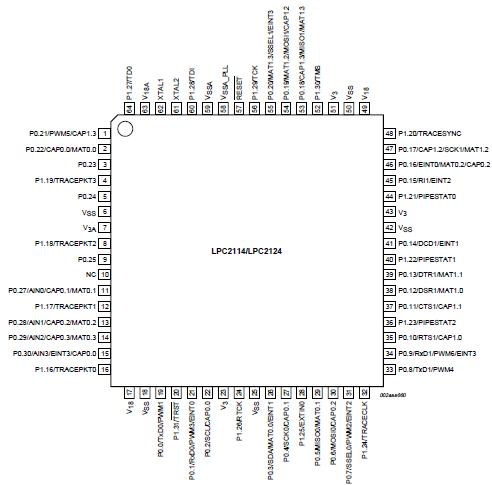 Specifications
|
Symbol |
Parameter |
Min |
Max |
Unit |
|
V18 |
Supply voltage, internal rail |
-0.5 |
+2.5 |
V |
|
V3 |
Supply voltage, external rail |
-0.5 |
+3.6 |
V |
|
V3A |
Analog 3.3 V pad supply voltage |
-0.5 |
4.6 |
V |
|
AVIN |
Analog input voltage on A/D related pins |
-0.5 |
5.1 |
V |
|
Vi |
DC input voltage, 5 V tolerant I/O pins[3][4] |
-0.5 |
6.0 |
V |
|
Vi |
DC input voltage, other I/O pins[2][3] |
-0.5 |
V3+0.5 |
V |
|
I |
DC supply current per supply pin[5] |
- |
100 |
mA |
|
I |
DC ground current per ground pin[5] |
- |
100 |
mA |
|
Tstg |
Storage temperature[6] |
-40 |
125 |
°C |
|
P |
Power dissipation (based on package heat transfer, not device power consumption) |
1.5 |
- |
W |
[1] The following applies to the Limiting values:
a) Stresses above those listed under Limiting values may cause permanent damage to the device.
This is a stress rating only and functional operation of the device at these or any conditions other than those described in Section 8 "Static characteristics" and Section 9 "Dynamic characteristics"of this specification is not implied.
b) This product includes circuitry specifically designed for the protection of its internal devices from the damaging effects of excessive static charge. Nonetheless, it is suggested that conventional precautions be taken to avoid applying greater than the rated maximum.
c) Parameters are valid over operating temperature range unless otherwise specified. All voltages
are with respect to VSS unless otherwise noted.
[2] Not to exceed 4.6 V.
[3] Including voltage on outputs in 3-state mode.
[4] Only valid when the V3 supply voltage is present.
[5] The peak current is limited to 25 times the corresponding maximum current.
[6] Dependent on package type.
DescriptionThe LPC2114/LPC2124 are based on a 16/32 bit ARM7TDMI-S™ CPU with real-time emulation and embedded trace support, together with 128/256 kilobytes (kB) of embedded high speed flash memory. A 128-bit wide memory interface and a unique accelerator architecture enable 32-bit code execution at maximum clock rate. For critical code size applications, the alternative 16-bit Thumb Mode reduces code by more than 30% with minimal performance penalty.
With their compact 64 pin package, low power consumption, various 32-bit timers,4-channel 10-bit ADC, PWM channels and 46 GPIO lines with up to 9 external interrupt pins these microcontrollers are particularly suitable for industrial control,medical systems, access control and point-of-sale. With a wide range of serial communications interfaces, they are also very well suited for communication gateways, protocol converters and embedded soft modems as well as many other general-purpose applications.

 LPC2114 Data Sheet